
Novel sharpeners to create cross-grind knife edges

a cross-grinding knife and edge technology, applied in the direction of gear teeth, gear teeth, gear manufacturing apparatus, etc., can solve the problems of repeating, fast and high precision, extremely difficult, time-consuming, etc., and achieve the effect of high effectiveness

Active Publication Date: 2011-02-10
EDGECRAFT
View PDF36 Cites 29 Cited by
  • Summary
  • Abstract
  • Description
  • Claims
  • Application Information

AI Technical Summary

Benefits of technology

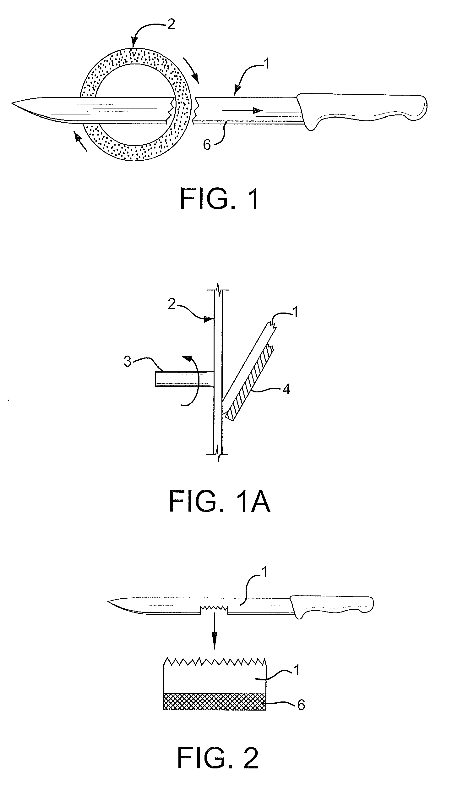
[0005]This creates edge irregularities that are pointed in both directions first as seen by viewing perpendicular to the knife edge line but also as viewed sighting in line with the cutting edge. The irregularities thus formed at the edge are very sharp but in addition the grind lines each leave sharp flutes that extend from the fine micro-serrations onto the surface of the small supporting facets on each side of the edge. The flutes assist in cutting. This type of edge is highly effective irrespective of whether the knife is pushed or pulled through the material being cut.
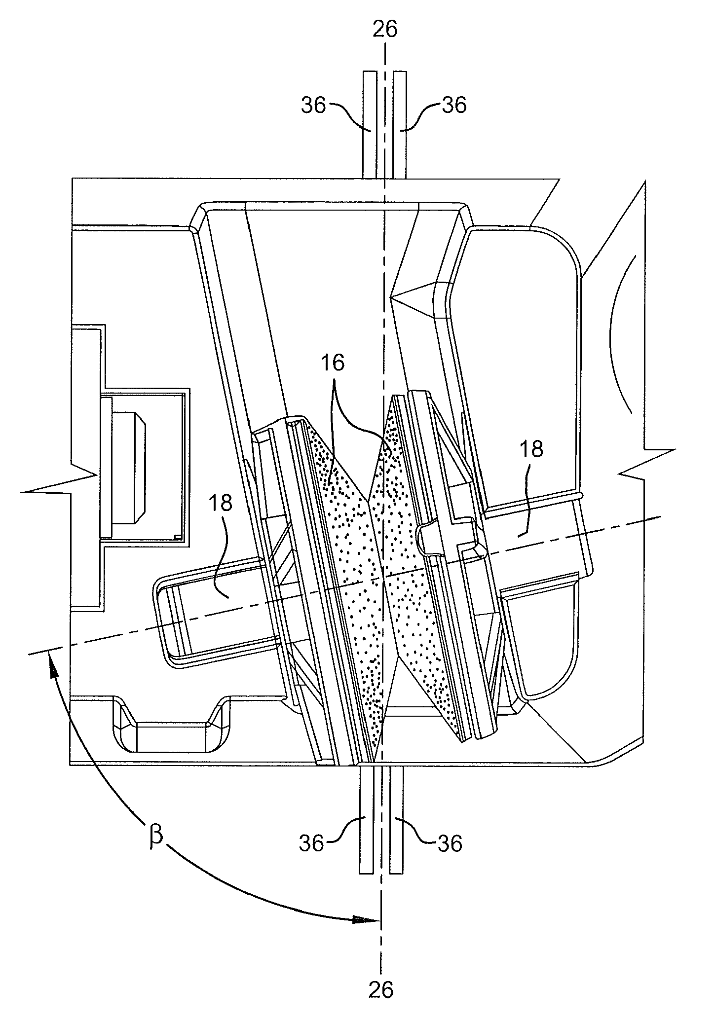
[0007]We have developed electrically powered sharpeners that can be used to create this specialized edge quickly, that can be followed by additional powered stages using finer abrasives to refine this geometry and sharpness of the structure created along the edge. Alternatively special manual sharpening means can be combined with these new electrical sharpeners to further refine the edge sharpness while maintaining this preferred edge structure and reducing the size of the edge structure. The combination of electrical and manual means is unique, surprisingly effective and a highly economical combination, resulting in a generally affordable means to sharpen a wide variety of knives leaving a very versatile multi-purpose cutting edge.

Problems solved by technology

In order to create this highly effective knife edge reproducibly, repeatedly, and quickly with high precision is extremely challenging.
But that is truly impractical and very time consuming even for those highly skilled in manual sharpening.

Method used


Image

  • Novel sharpeners to create cross-grind knife edges
  • Novel sharpeners to create cross-grind knife edges
  • Novel sharpeners to create cross-grind knife edges

Examples


Embodiment Construction

[0017]It is common practice when sharpening with conventional abrasive wheels to hold the metallic knife edge against a rotating abrasive wheel and to drive the abrasive in a specific single direction so that the abrasive surface is directed to move away from the knife edge as it is sharpened. That motion can under ideal conditions create a very thin, sharp, and uniform edge. When the sharpening abrasive is driven across the edge in the opposite direction, that is into the edge (not away from the edge), a highly distorted undesirable burr can be created along the edge facet, leaving a less desirable edge. The burr created by that reverse grinding motion we have shown can however be quickly removed by a few strokes where the abrasive moves away from the edge, removing the burr debris from the facets and edge, leaving an improved cutting edge.

[0018]The efficient powered sharpening means that has been developed by these inventors can create this improved type of edge repeatedly with hi...


PUM

PropertyMeasurementUnit
Angleaaaaaaaaaa
Angleaaaaaaaaaa
Angleaaaaaaaaaa

Abstract

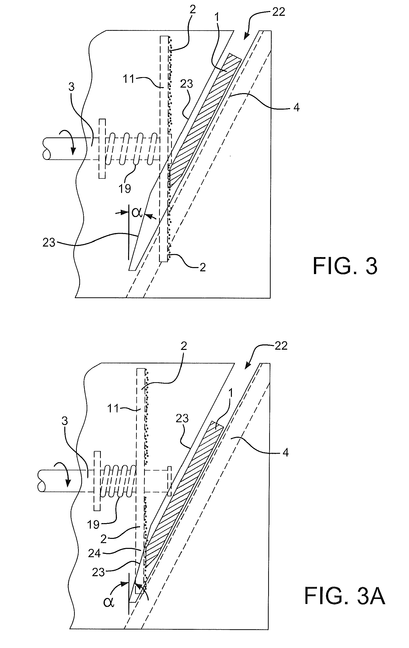
A sharpener for creating cross-grind knife edges includes a nominally flat annular abrasive sharpening member which could be a ring or a disk and is rotated about its center and held against a moving knife edge facet to simultaneously and sequentially abrade the knife edge at multiple locations on the abrasive member. The disk may be slidably mounted on a shaft in opposition to a spring restraining force. The disk is nominally disposed in a vertical orientation. The sharpener may include multiple stages including a manual stage having a pair of off axis conical shaped rotatable abrasive coated disks which have abrading lines on opposing facets which are not parallel but cross and intersect in a crossing pattern at the blade edge.

Description

CROSS REFERENCE TO RELATED APPLICATION[0001]This application is based on provisional application Ser. No. 61 / 232,065, filed Aug. 7, 2009, all of the details of which are incorporated herein by reference thereto.BACKGROUND OF INVENTION[0002]This disclosure describes unique powered and manual sharpening means using abrasives to rapidly create a highly effective cutting edge on knives and similar cutting blades. Much has been written about means to create extraordinarily sharp edges on knives by creating geometrically perfect facets on each side of a knife edge that meet with high precision to create edges only a few microns in width. Further advances have been made in the old art of steeling an edge using modern technology to create highly reproducible micro-serrated edges along an already sharpened edge. This disclosure is about a unique and highly effective knife edge structure and more specifically about novel sharpening means to create such structure.[0003]In spite of the technica...

Claims


Application Information

Patent Timeline
IPC IPC(8): B24B3/54B24D15/08
CPCB24B3/54
Inventor ELEK, BELAFRIEL, SR., DANIEL D.FRIEL, JR., DANIEL D.
Owner EDGECRAFT
Learn More