Method for preparing recipient site and implanting allogenic bone graft

Active Publication Date: 2011-02-10
SAWATARI YOH +1
View PDF14 Cites 3 Cited by
  • Summary
  • Abstract
  • Description
  • Claims
  • Application Information

AI Technical Summary

Problems solved by technology

As described, the process is routine yet difficult.
The most time consuming and critical aspect of the procedure involves the adaptation of the section of iliac crest to a deficient mandible.
If there is poor adaptation,

Method used


Image

  • Method for preparing recipient site and implanting allogenic bone graft
  • Method for preparing recipient site and implanting allogenic bone graft
  • Method for preparing recipient site and implanting allogenic bone graft

Examples


Embodiment Construction

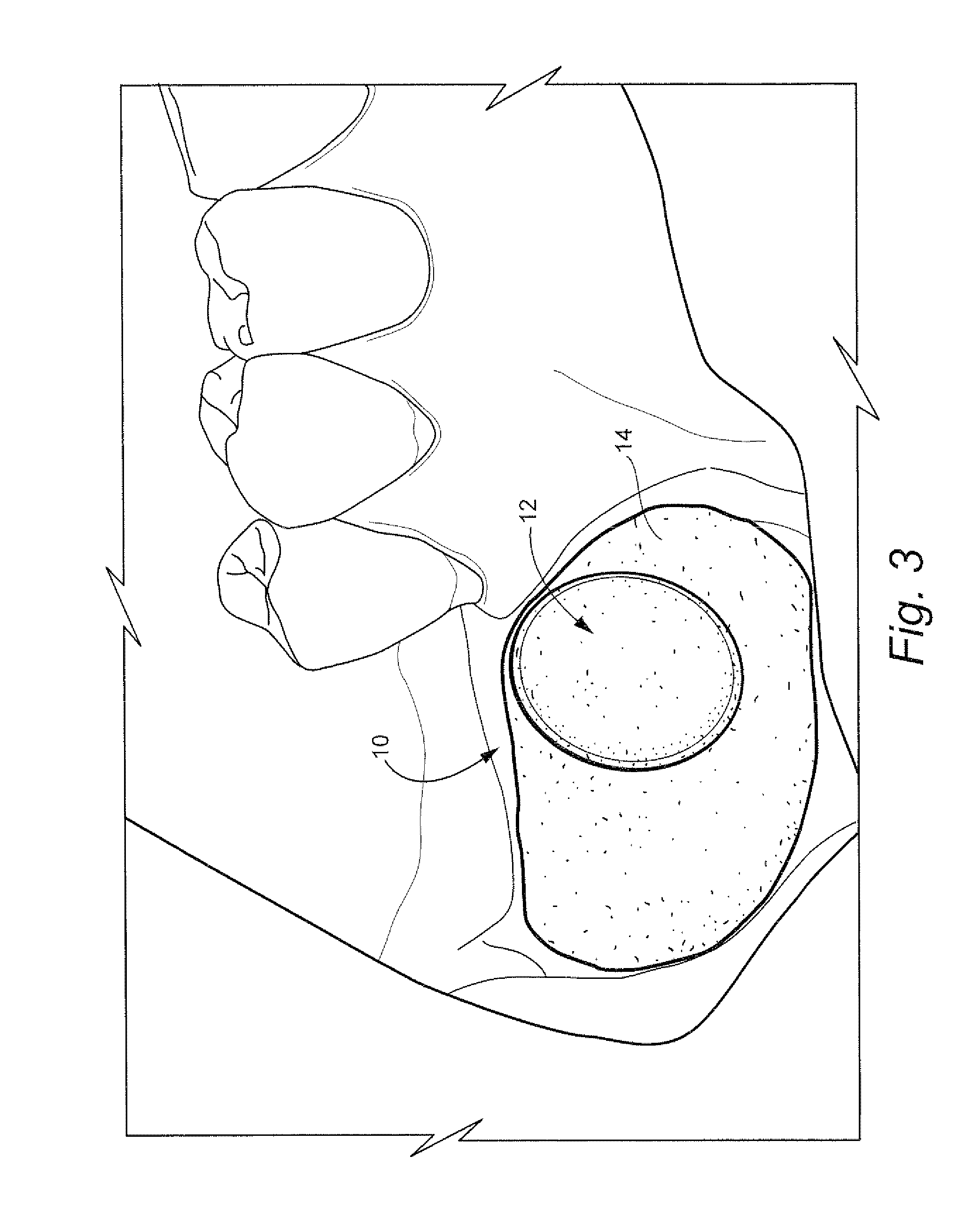
[0012]To address difficulties of contouring a section of iliac bone for placement in a recipient site, in accordance with the invention, instead of contouring the allogeneic bone, the patient recipient site in the native jaw is manipulated to have a shape corresponding to that of the allogeneic bone section.

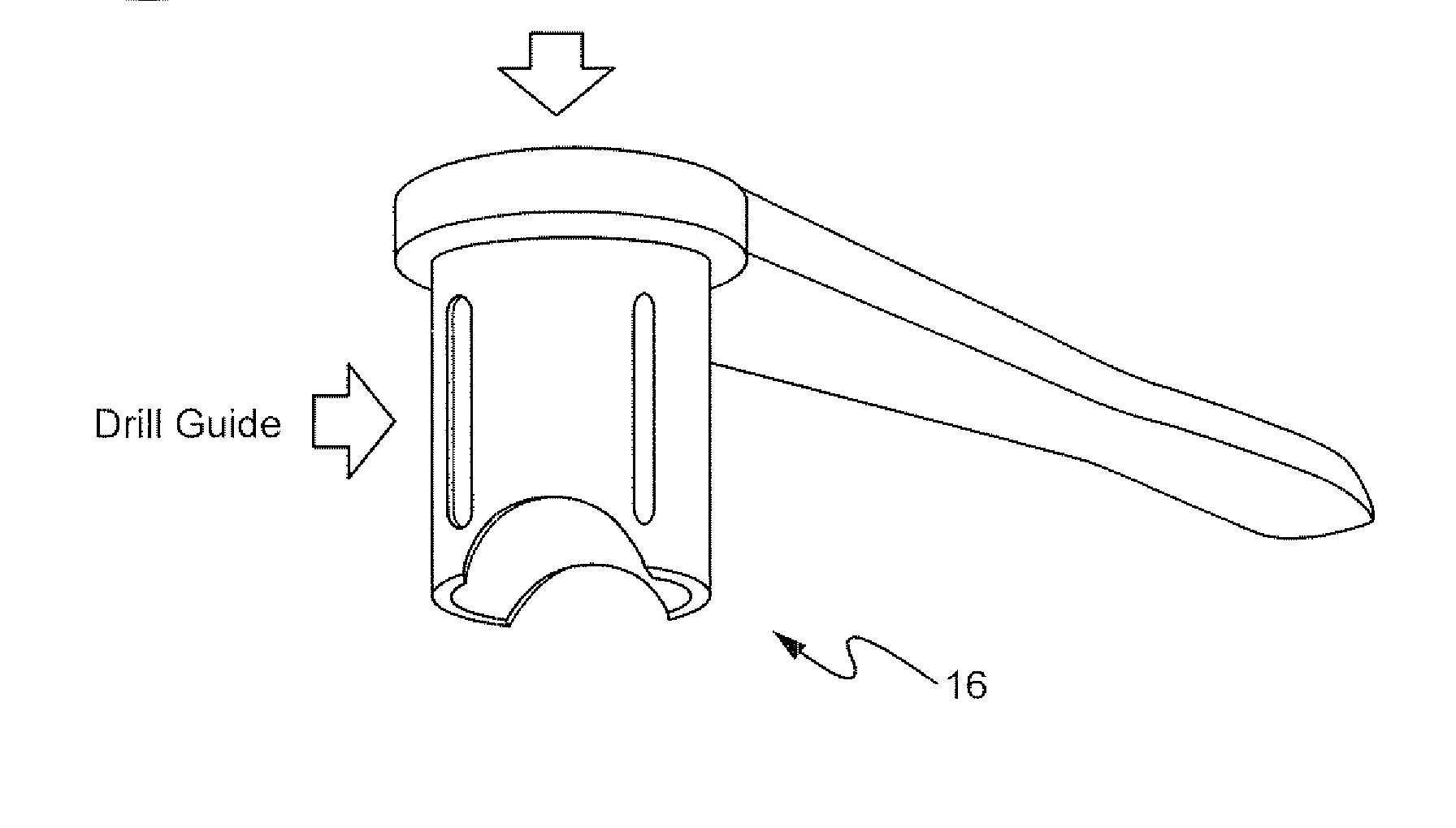
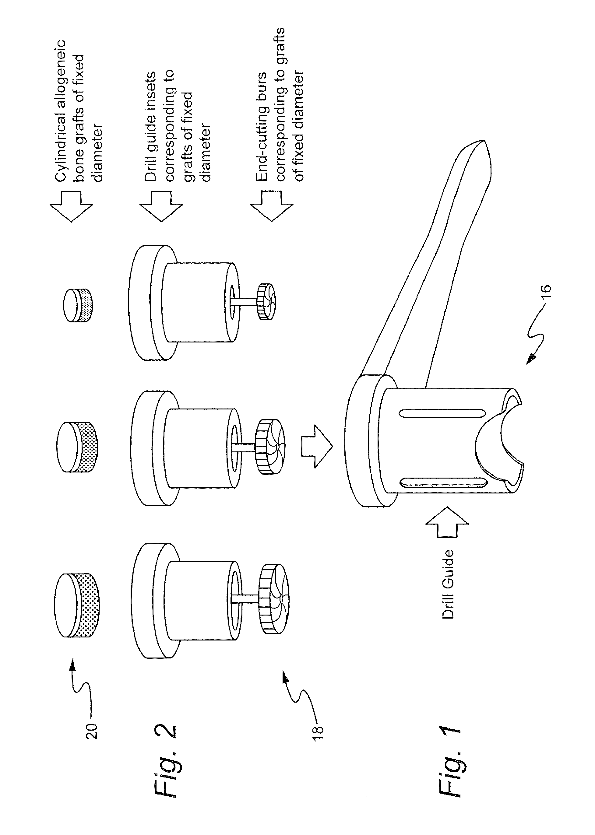
[0013]In an example embodiment of the invention, the manipulation of the recipient site 10 involves the preparation of a cylindrical docking area 12 in which a cylindrical section of allogeneic bone of standardized diameter can be placed. Recipient sites may be of varying size. Therefore, a plurality of standardized allogeneic bone diameters can be contemplated and prepared. For example, the diameter of the graft may range from about 3 mm to 20 mm. Moreover, the height or thickness of the graft may range from about 2 mm to 10 mm. As noted, the graft material will be allogeneic bone. However, in addition, it may be defined as cortical, cancellous, or corticocancellous. Based on an...


PUM


Abstract

A method of fixating allogeneic bone to an area of deficient bone in the jaws comprising: exposing the area of deficient bone by incising and retracting soft tissue; selecting a drill bit having a diameter corresponding to the area of deficient bone to receive donor bone; contacting the selected drill bit with the exposed deficient bone to form a generally cylindrical seat for receiving the donor bone; selecting a section of donor bone having a generally cylindrical shape and circular cross-section corresponding to said formed seat; fixating the donor bone to the formed seat with at least one screw; and closing the soft tissue to cover the previously exposed deficient bone.

Description

CROSS-REFERENCE TO RELATED APPLICATION[0001]This application claims the benefit of Provisional Application No. 61 / 064,651, filed Mar. 18, 2008, the entire content of which is hereby incorporated by reference in this application.BACKGROUND OF THE INVENTION[0002]The use of allogeneic grafting has become a standard methodology to increase bone volume in deficient areas of the maxilla and mandible. The purpose of this grafting procedure is to prepare the patient for the eventual restoration of the patient's function and esthetics with dental implants.[0003]Conventionally, this procedure involves the surgical exposure of an area of deficient bone in the jaws, removal of a section of freeze dried iliac crest from a tissue bank, contouring the section from the iliac crest to follow the anatomical curvature of the target area of the jaw in which it is to be implanted and adapting the section of iliac crest to passively rest on the jaw with maximum contact with the existing bone matter. The ...

Claims


Application Information

Patent Timeline
IPC IPC(8): A61B17/16
CPCA61B17/1673A61B17/176A61B17/86A61C1/082A61C8/0089A61F2310/00359A61F2/2803A61F2/2846A61F2002/30224A61F2002/30616A61F2230/0069A61F2/28
Inventor SAWATARI, YOHPELEG, MICHAEL
Owner SAWATARI YOH
Why Eureka
Try Eureka