Dual Glazed Framing System for Encapsulating Translucent Insulating Particulate Material and Method of Making Same

a technology of encapsulating translucent insulating particulate material and double glazing, which is applied in the field of skylight, can solve the problems of significant unwanted heat loss, lack of insulating value of other building materials found in ceilings, roofs or walls of structures, and energy draining of heat that passes through the panels

Inactive Publication Date: 2011-02-17
BACK MARK A +2
View PDF11 Cites 15 Cited by
  • Summary
  • Abstract
  • Description
  • Claims
  • Application Information

AI Technical Summary

Benefits of technology

[0006]To these ends, a dual glazed framing system for increasing the insulating value of skylights or other like panels is provided. The dual glazed panel framing system includes a first glazing panel and an opposing second glazing panel. The frame that supports the panels has a first ledge that is adapted to receive the first glazing panel and an opposing second ledge adapted to receive the opposing second glazing panel. In that manner, an insulating cavity is formed between the first glazing panel and the second glazing panel. The insulating cavity of the dual glazed framing system is filled with a translucent insulating particulate material. In one embodiment, the translucent insulating particulate material is an aerogel such as a Nanogel brand sold by Cabot Industries, Boston, Mass.

Problems solved by technology

While such skylights can provide light to interior space without the use of any other energy source, or provide desirable aesthetics, they typically lack the insulating value of the other building materials found in the ceilings, roofs, or walls of a structure.
Therefore, while skylights or other like panels may provide desirable aesthetic qualities and energy savings with regard to the consumption of energy for the production, they are often an energy drain as to the heat that passes through the panels.
This circulation cycle tends to considerably amplify unwanted heat loss by convection.
Additionally, due to typical orientation of skylights, there is often significant unwanted heat loss in the form of radiation to the night sky.

Method used


Image

  • Dual Glazed Framing System for Encapsulating Translucent Insulating Particulate Material and Method of Making Same
  • Dual Glazed Framing System for Encapsulating Translucent Insulating Particulate Material and Method of Making Same
  • Dual Glazed Framing System for Encapsulating Translucent Insulating Particulate Material and Method of Making Same

Examples


Embodiment Construction

[0022]Although the invention will be described in connection with certain embodiments, the invention is not limited to practice in any one specific type of skylight or other like panel. The description of the embodiments of the invention is intended to cover all alternatives, modifications, and equivalent arrangements as may be included within the spirit and scope of the invention as defined by the appended claims. In particular, those skilled in the art will recognize that the components of the embodiments of the invention described herein could be arranged in multiple different ways.

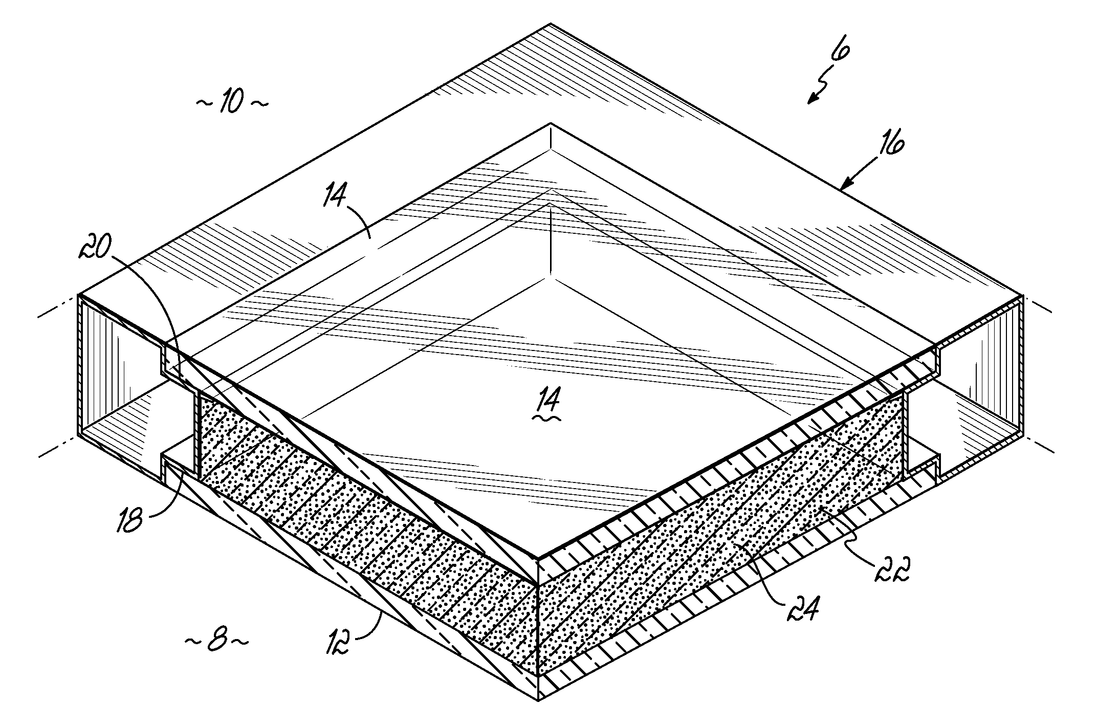
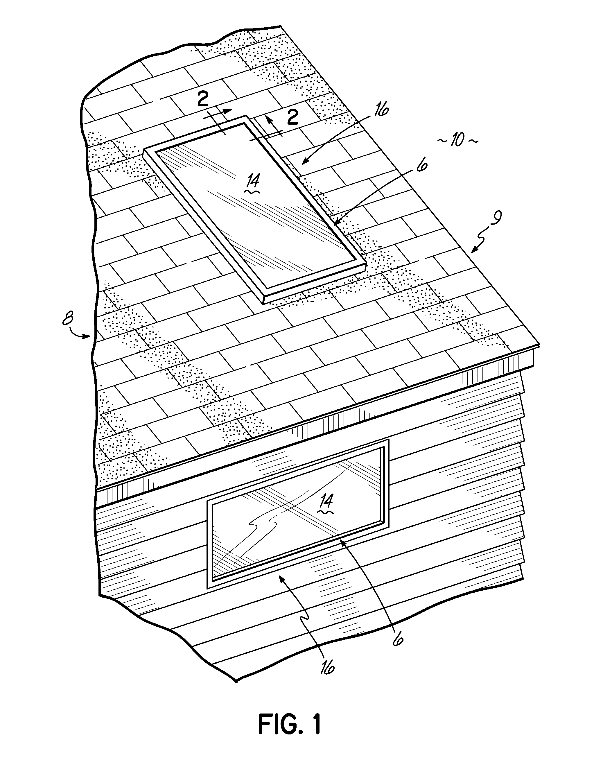
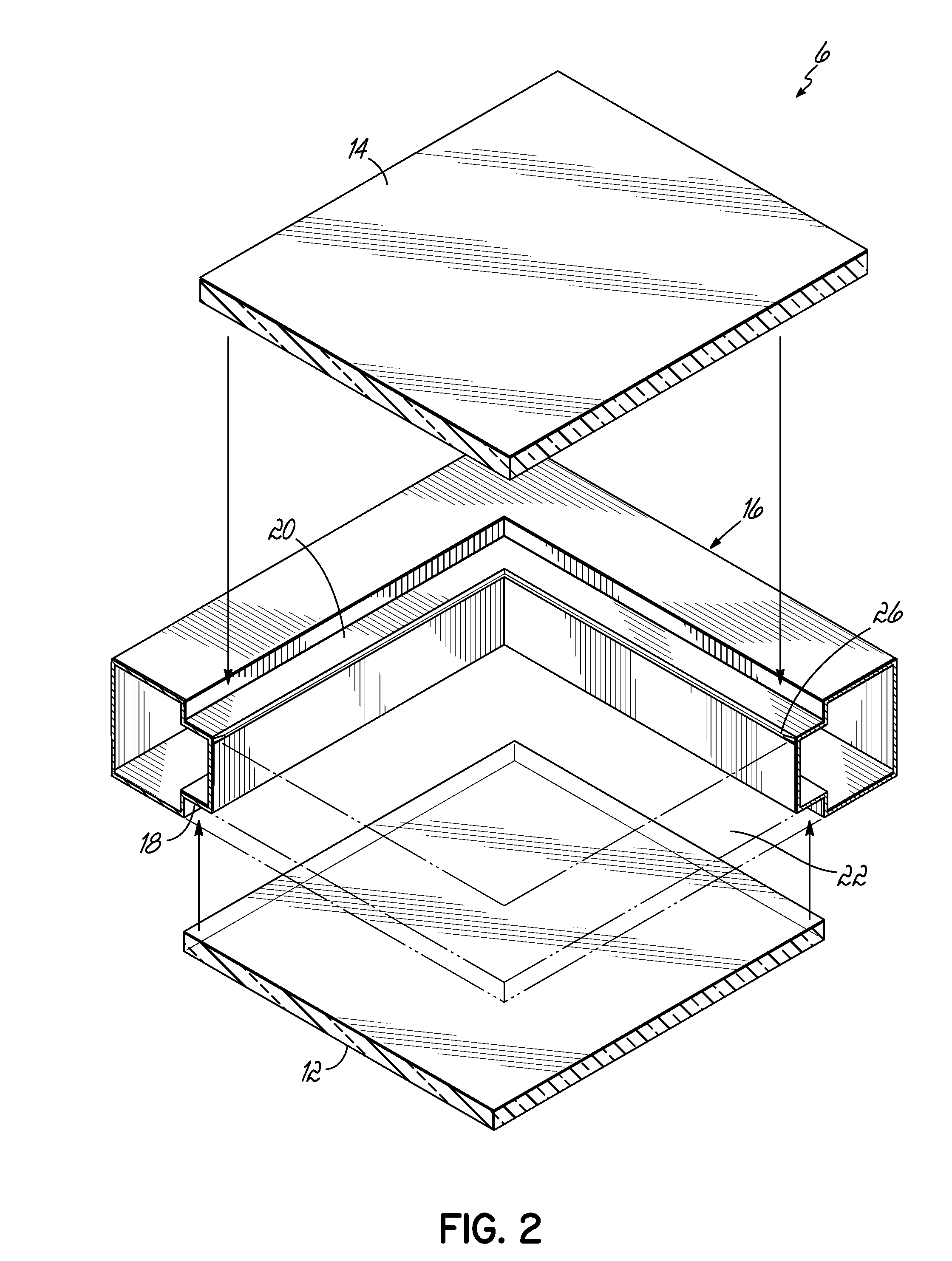
[0023]Referring now to the drawings, specifically FIGS. 1 and 2, a dual glazed framing system 6 is provided. The dual glazed framing system 6 will be described herein with respect to an interior portion 8 which, for example, may communicate with an interior space of a dwelling, and an exterior portion 10 which, for example, may communicate with a space exterior to a dwelling.

[0024]With reference to FIG...


PUM

PropertyMeasurementUnit
translucentaaaaaaaaaa
flexibleaaaaaaaaaa
volumeaaaaaaaaaa

Abstract

A skylight or other like panel comprising a dual glazed framing system is provided. The dual glazed framing system includes opposing glazing panels, a frame with supporting ledges, and translucent insulating particulate material is encapsulated in a insulating cavity defined by the frame and the opposing panes. A movable fill guide is provided and allows for the compression of the translucent insulating particulate material. A method of creating a dual glazed framing system filled with translucent insulating particulate material is also provided.

Description

CROSS-REFERENCE TO RELATED APPLICATIONS[0001]This application claims the benefit of U.S. Provisional Application No. 61 / 234,143, filed Aug. 14, 2009 the disclosure of which is hereby incorporated by reference.TECHNICAL FIELD[0002]The present invention generally relates to a skylight or other like panel comprising a dual glazed framing system, the dual glazed framing system encapsulating translucent insulating particulate material. The present invention further relates to a method of creating a dual glazed framing system filled with translucent insulating particulate material.BACKGROUND[0003]It is often desirable to use skylights or other like panels in the construction of structures that have an interior space that will be heated or cooled, depending on the season, and an exterior surface that is exposed to the elements. While such skylights can provide light to interior space without the use of any other energy source, or provide desirable aesthetics, they typically lack the insula...

Claims


Application Information

Patent Timeline
Patent Type & Authority Applications(United States)
IPC IPC(8): E06B7/12B21D47/00
CPCE04D13/03E06B3/24Y10T29/49623E06B3/6775E06B3/6715
Inventor BACK, MARK A.RILEY, J. MICHAELWELSH, JOHN E.
Owner BACK MARK A
Why Eureka
Try Eureka