Rotary power tool operable in first speed mode and a second speed mode

a technology of rotary power tools and speed modes, which is applied in the direction of manufacturing tools, portable power tools, transportation and packaging, etc., can solve the problems of high cost of precision ball bearings used to stabilize ring gears, high cost of precision ball bearings, and high vibration and vibration-associated nois

Inactive Publication Date: 2011-02-17
ROBERT BOSCH GMBH
View PDF6 Cites 31 Cited by
  • Summary
  • Abstract
  • Description
  • Claims
  • Application Information

AI Technical Summary

Benefits of technology

[0003]It is therefore an object of this invention to overcome the disadvantages of the prior art by describing low cost means for stabilizing the gear that is used for switching speeds in a multi-speed transmission for a rotary power tool. The inventive rotary power tool is operable in a first speed mode and a second speed mode and has a motor shaft, a driveshaft, and a transmission for transmitting torque from the motor

Problems solved by technology

Without support structures to stabilize this ring gear, it would be susceptible to vibration and vibration-associated noise.
However support structures tend to introduce fricti

Method used


Image

  • Rotary power tool operable in first speed mode and a second speed mode
  • Rotary power tool operable in first speed mode and a second speed mode
  • Rotary power tool operable in first speed mode and a second speed mode

Examples


second embodiment

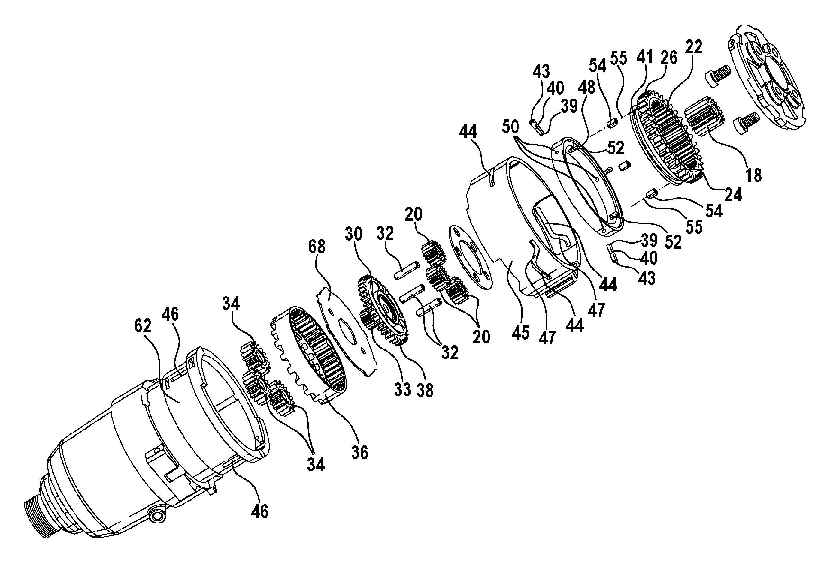
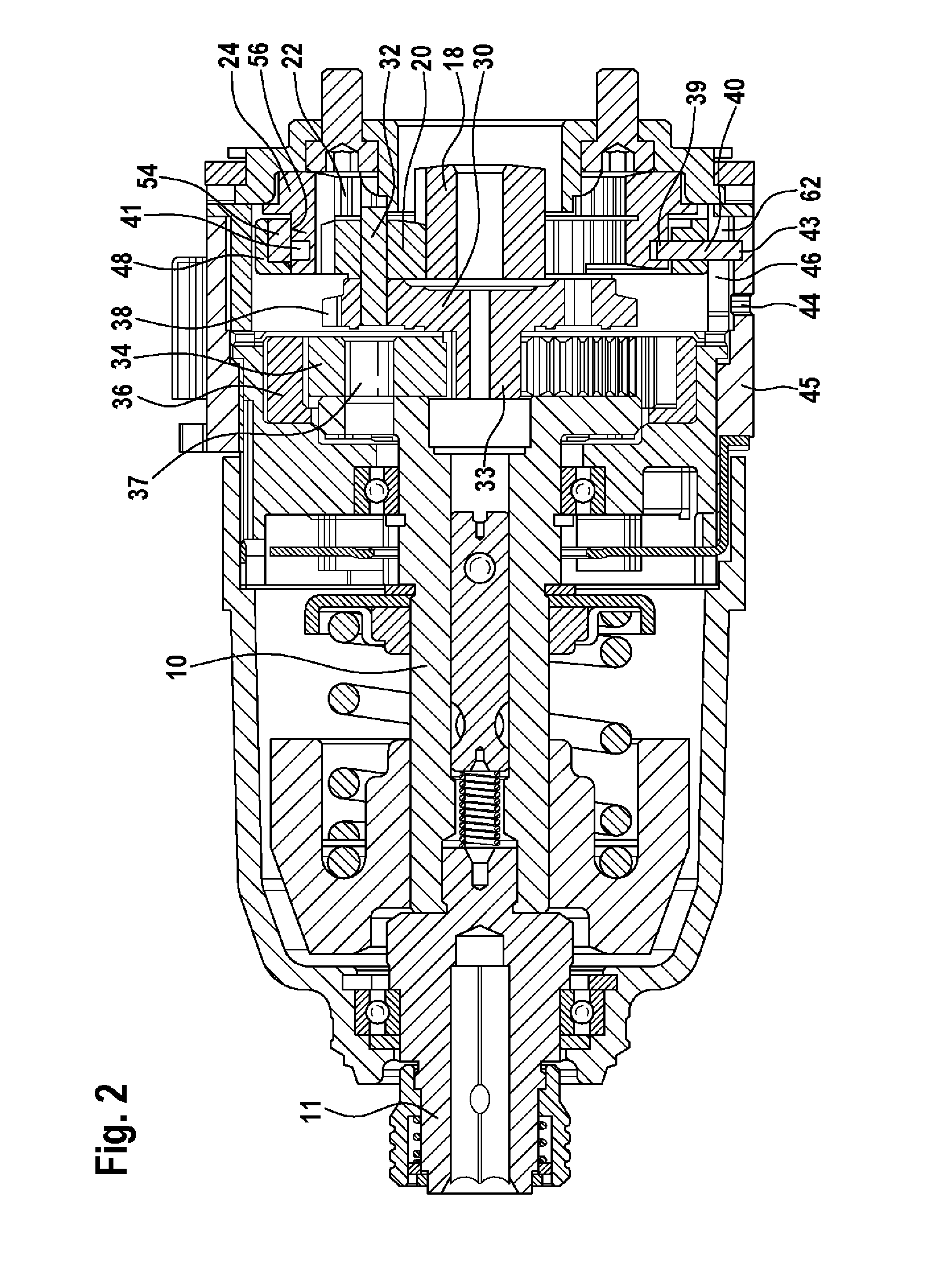
[0063]The second embodiment utilizes five planetary gears (not shown) rather than three. Twelve rollers 76 are used as bearing members in this embodiment. While these differences provide certain advantages, these must be balanced against various drawbacks, in so far as more planetary gears would cost more and more bearing members means there will be corresponding increases in the amount of friction with the ring gear 74. However, when considering the power loss associated with the friction, the power losses to vibration tend to greater and therefore outweigh this disadvantage. Although incorporating more than twelve bearing members is also possible, to a certain extent the possibility of increasing the number of rollers 76 even further is limited based on space limitations as to how many bearing members can be accommodated by the support ring 70.

[0064]To minimize the overall vibration in the system, it is preferred if the number of planetary gears and the number of rollers 76—in thi...

first embodiment

[0067]To provide insulation from the heat generated by the axial adjustment means which travel within the ring gear 74, the pins 40 of the first embodiment are replaced with an inner pin 88 within the metal inner ring 78 and the outer pin 90 within the plastic outer ring 80. Both pins 88, 90 are preferably made of metal, but the pins 88, 90 are also spatially separated so that heat from the inner pin 88 generated by contact with the circumferential groove 92 in the ring gear 74 is dissipated by the inner ring 78 before it can reaches the outer pin 90. In practice, the spatial separation increases the amount of time the tool must be continuously operated before the temperature of the gearbox housing 62 reaches a plateau temperature.

[0068]Although for the purposes of increasing the holding force on outer pin 90, the pin 90 penetrates outer ring 80 and contacts inner ring 78, a blind hole can alternatively be used, so that there is even greater insulation between the inner 88 and outer...


PUM


Abstract

A rotary power tool operable in a first speed mode and a second speed mode comprising a motor shaft (6), a driveshaft (10) with an axis of rotation (42), a gear (24, 74) that is a component of a transmission (8) for transmitting torque from the motor shaft (6) to the driveshaft (10), a support member (48, 70), at least one bearing member (54, 76) which contacts the gear (24, 74), wherein the gear (24, 74), the support member (48, 70) and the at least one bearing member (54, 76) form an assembly that is in a first position along the axis of rotation (42) when the tool is operating in the first speed mode and is in a second position along the axis of rotation (42) when the tool is operating in the second speed mode, and wherein the at least one bearing member (54, 76) protrudes from the support member (48, 70) in the direction of the gear (24, 74) and rotates when the gear (24, 74) rotates.

Description

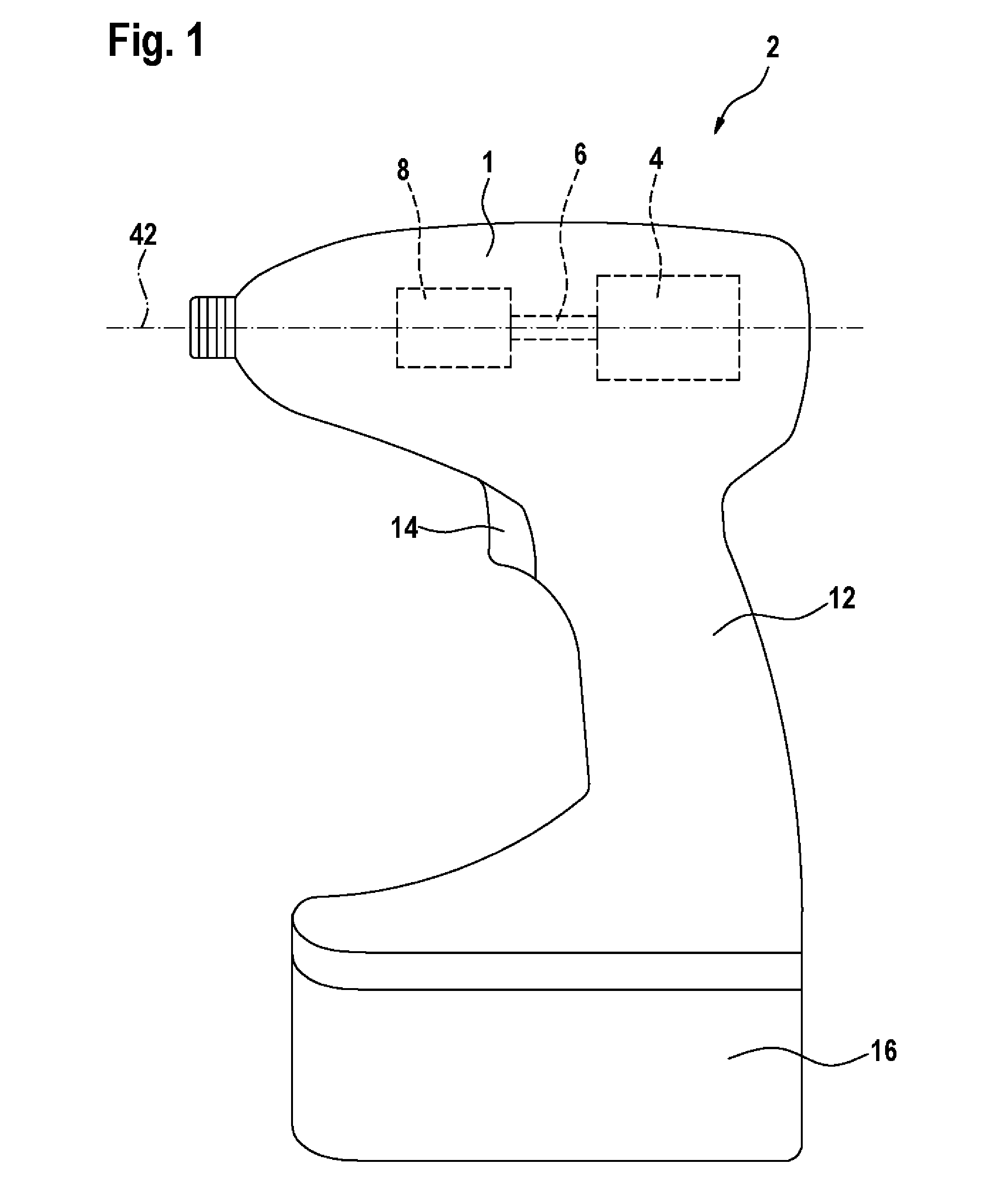
PRIOR ART[0001]The present invention relates to rotary power tools and in particular to mechanisms for controlling the speed of a rotary power tool output shaft. U.S. Pat. No. 7,124,839 discloses a multi-speed transmission for a rotary power tool mediated by two sets of planetary gears. The speed of the output shaft is determined by adjusting the axial position of one of the ring gears. In a first axial position, the ring gear cannot rotate, so both planetary gear sets contribute to speed reduction, and the tool operates in low speed mode. In a second axial position, the ring gear is free to rotate and is coupled with the sun gear of the second planetary gear set. As a result, there is no speed reduction by the first set of planetary gears and the tool operates in a high speed mode.[0002]Without support structures to stabilize this ring gear, it would be susceptible to vibration and vibration-associated noise. However support structures tend to introduce friction which generates hea...

Claims


Application Information

Patent Timeline
IPC IPC(8): B25F5/00
CPCB25B21/00F16H2200/2007F16H2200/0034B25F5/001
Inventor LEONG, CHI HOENG, SENG LOONGBROGLI, DANIEL
Owner ROBERT BOSCH GMBH
Why Eureka
Try Eureka