Spray nozzle assemblies

Active Publication Date: 2011-02-17
MORGAN STUART +1
View PDF15 Cites 3 Cited by
  • Summary
  • Abstract
  • Description
  • Claims
  • Application Information

AI Technical Summary

Benefits of technology

[0008]The invention in one aspect is the provision of housings within a spray nozzle assem

Problems solved by technology

In general spray nozzles which are provided with swirl chambers and orifice discs have these components manufactured from tungsten carbide or the like which is very hard but also brittle and prone to damage when dropped or other wise roughly treated during assembly and disassembly.
When ordinary spray nozzles are used for

Method used


Image

  • Spray nozzle assemblies
  • Spray nozzle assemblies

Examples


first embodiment

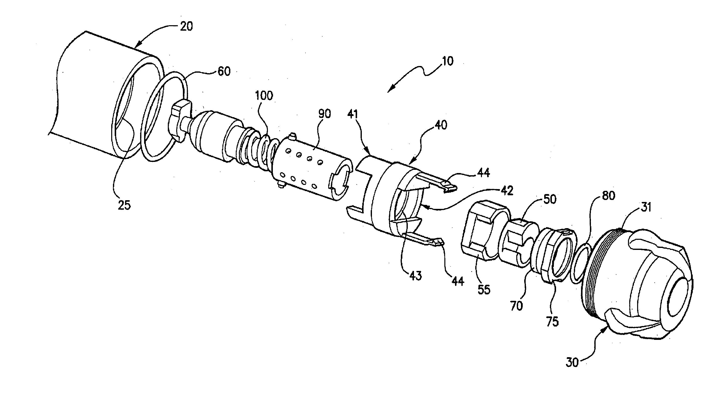
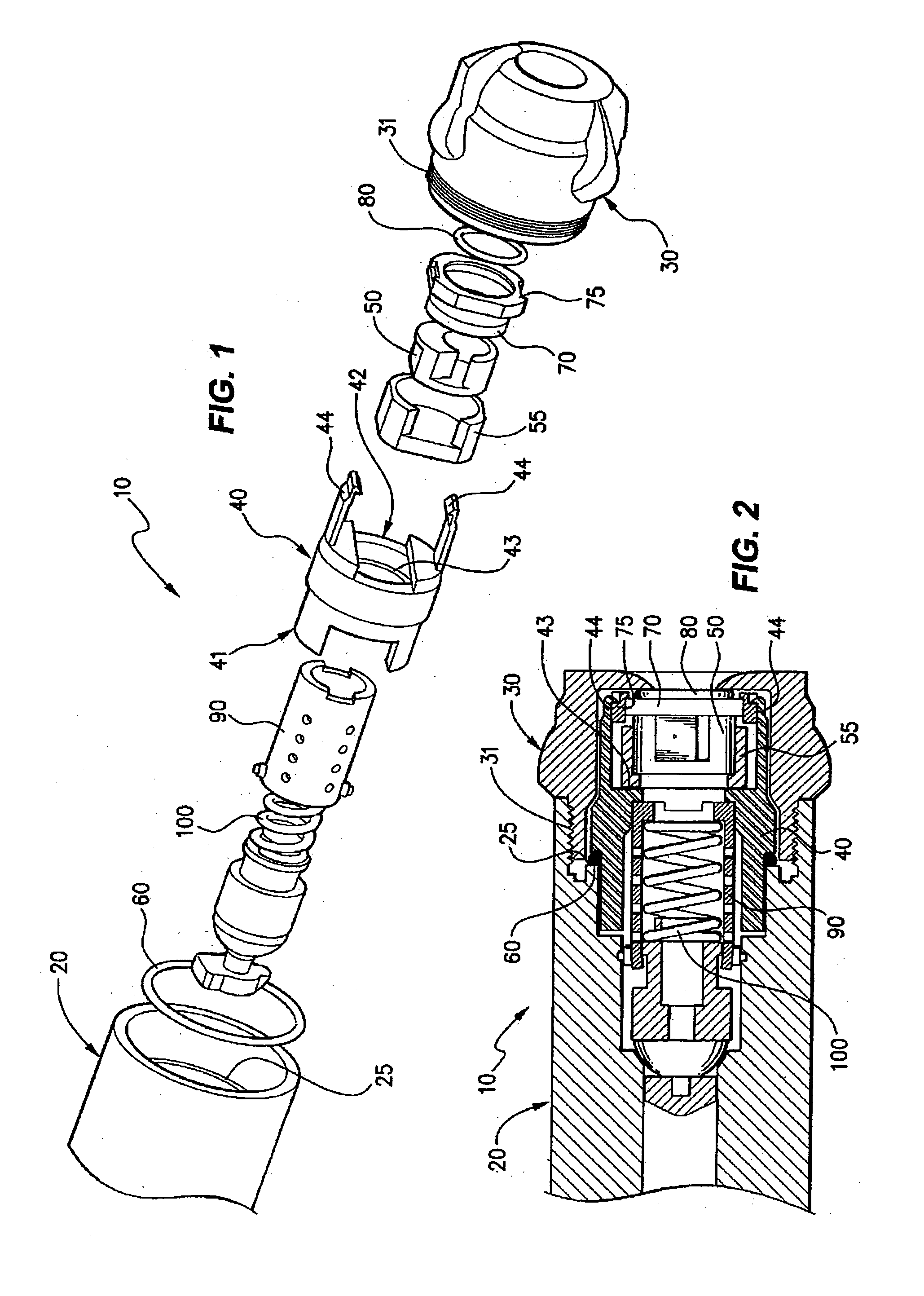
[0025]In the invention 10 a spray nozzle is provided, within its lance adapter 20 and retainer cap 30 components, with a clasp device 40 which at a first end 41 seats compressively against an O ring 60 located in sealing arrangement within the lance adapter.

[0026]An opposing end of the clasp 42 is provided with a seat 43 for a swirl chamber 50 and orifice disc 70 assembly, the clasp also being provided with arm members 44 which pass over the wear parts and compressively abut an O ring 80 within the retainer cap which provides a seal.

[0027]During use of such a spray nozzle it is common for the material being sprayed to adhere to the contacting components however with the device of the invention the provision of this clasp permits the wear parts to be simply removed upon rotation of the clasp thereby avoiding the damage to the wear parts caused by the conventional pressing out of the wear parts by an arbor press or other such means.

[0028]The swirl chamber 50 is located within a housin...

second embodiment

[0033]In the invention a check valve is provided within the spray nozzle assembly. In this embodiment the first end 41 of the clasp passes generally over the perforated sleeve 90 covering the valve spring 100. This first end of the clasp in turn seats compressively against an O ring 60 located against a shoulder 25 within the lance adapter 20 to form a seal.

[0034]The lance adapter 20 and end cap 30 engage by means of a screw thread 31 located within one end of the lance adapter and the exterior of one end of the end cap the arrangement being such that when screw connection of these components has been effected no external thread is present which could be damaged by contact.

[0035]Whilst we have, in this specification, described one general form of a spray nozzle and one particular arrangement of the nozzle with a check valve, it will be understood that other spray nozzle forms, which operate in the same manner as that described, can readily be utilised in the invention.


PUM


Abstract

A spray nozzle assembly includes a body and a spray nozzle retainer cap, and further including a device for protecting wear components from damage. Preferably, housings are provided within the spray nozzle assembly for protecting wear components, such as a swirl chamber and an orifice disc from damage. A sealing device is included within the nozzle assembly, which is subject to only compressive forces.

Description

AREA OF THE INVENTION[0001]This invention relates in general to spray nozzle assemblies and in particular to the type of spray nozzle having a check valve which is specifically adapted to be used with spray drying nozzles, but could also be used in association with other nozzles.BACKGROUND TO THE INVENTION[0002]For ease of description, we shall refer to such a spray nozzle assembly in terms of one associated with spray drying of milk.[0003]In general spray nozzles which are provided with swirl chambers and orifice discs have these components manufactured from tungsten carbide or the like which is very hard but also brittle and prone to damage when dropped or other wise roughly treated during assembly and disassembly.[0004]When ordinary spray nozzles are used for spray drying milk a certain percentage of the liquid simply fell as drops from the nozzles, without being atomized, and this material could well lead to pollution of the product.[0005]To avoid this problem a unitary check va...

Claims


Application Information

Patent Timeline
IPC IPC(8): B05B1/34
CPCB01D1/18B05B1/3006B05B1/3426B05B15/18
Inventor MORGAN, STUARTMORGAN, SEAN
Owner MORGAN STUART
Why Eureka
Try Eureka