Linear electromagnetic machines

Inactive Publication Date: 2011-02-17
DENNE PHILLIP RAYMOND MICHAEL
View PDF8 Cites 7 Cited by
  • Summary
  • Abstract
  • Description
  • Claims
  • Application Information

AI Technical Summary

Benefits of technology

[0032]Embodiments of the invention seek to provide an economical means of constructing a cylindrical linear electrical machine in which the limitations on the diameter and mass of the magnetic armature are overcome so that large thrusts and continuous power outputs may be produced if required.
[0033]Embodiments of the invention seek to ensure that the backing iron remains equidistant from the central axis, that the air gap distance is minimised and that the magnetostatic forces are radially balanced.
[0034]Embodiments of the invention seek to provide an economical means of building a cylindrical linear electrical machine in which the cost and complexity of the machine does not increa

Problems solved by technology

This is not a simple matter if the core of the armature consists of a stack of disc magnets, because there is a practical limitation on their diameter that is set by the need to sinter the most common form of permanent magnet material under great pressure.
As the unit size of a powerful permanent magnet is increased, it becomes more dangerous to handle during the process of building the motor.
The large number of components and of assembly operations leads to an inherent unreliability.
There is another difficulty in that the interconnections stand proud of the remainder of the

Method used


Image

  • Linear electromagnetic machines
  • Linear electromagnetic machines
  • Linear electromagnetic machines

Examples


Embodiment Construction

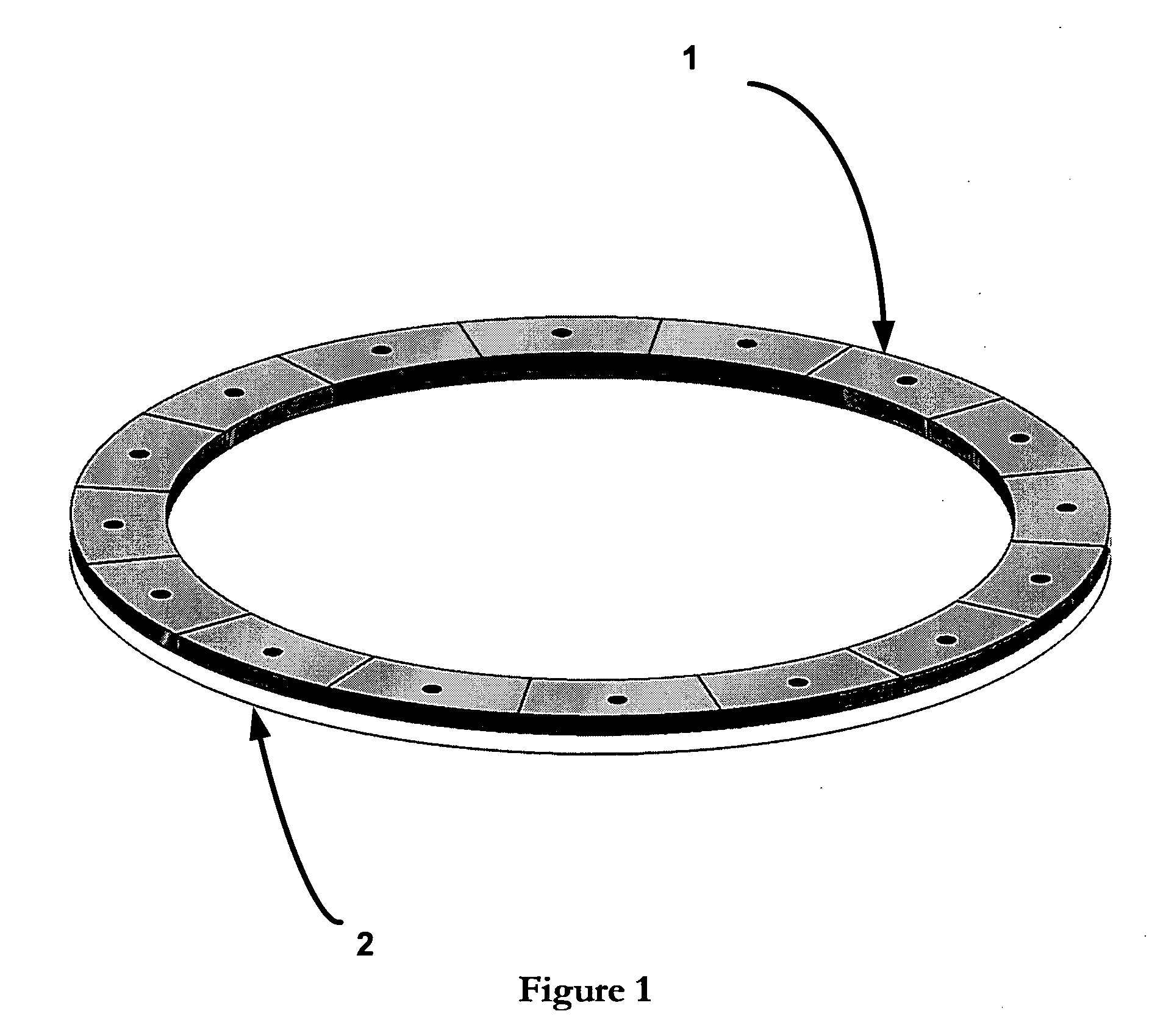
[0055]Referring to FIG. 1, a plurality of separate magnetic segments 1 are shown to be provided, and are pinned and bonded to a lower pole piece 2.

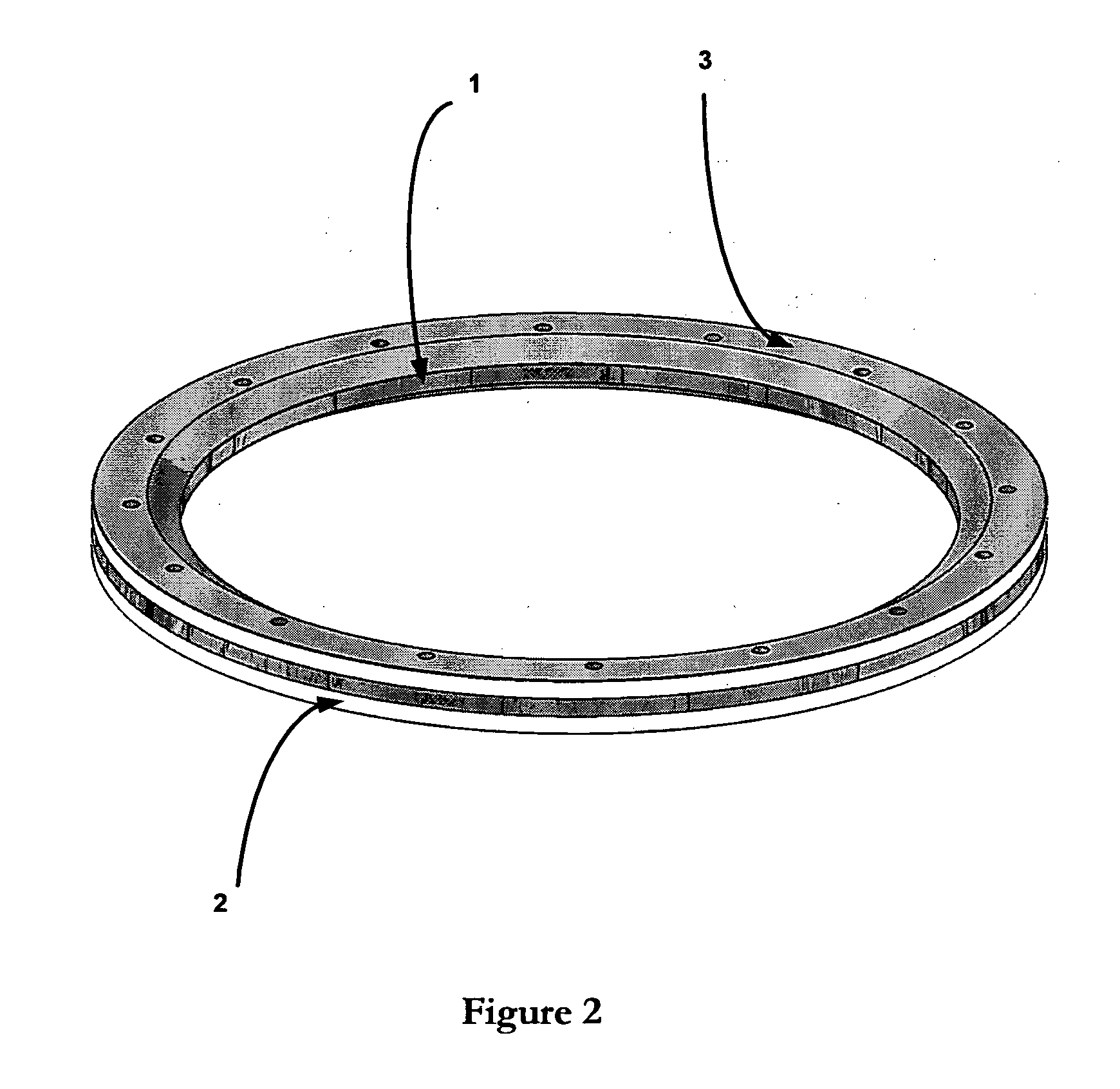
[0056]FIG. 2 shows how an upper pole piece ring 3 is fitted to the array of magnetic segments 1, so as to produce a complete force unit. The inwards taper of the rings (which reduces the leakage flux) is clearly visible in the diagram.

[0057]FIG. 3 shows how the required number of force units (having components 1, 2 and 3 as previously described with reference to FIGS. 1 and 2) are stacked with like poles opposing and are clamped between two non-magnetic end pieces 4 and 5, so as to form a complete armature array.

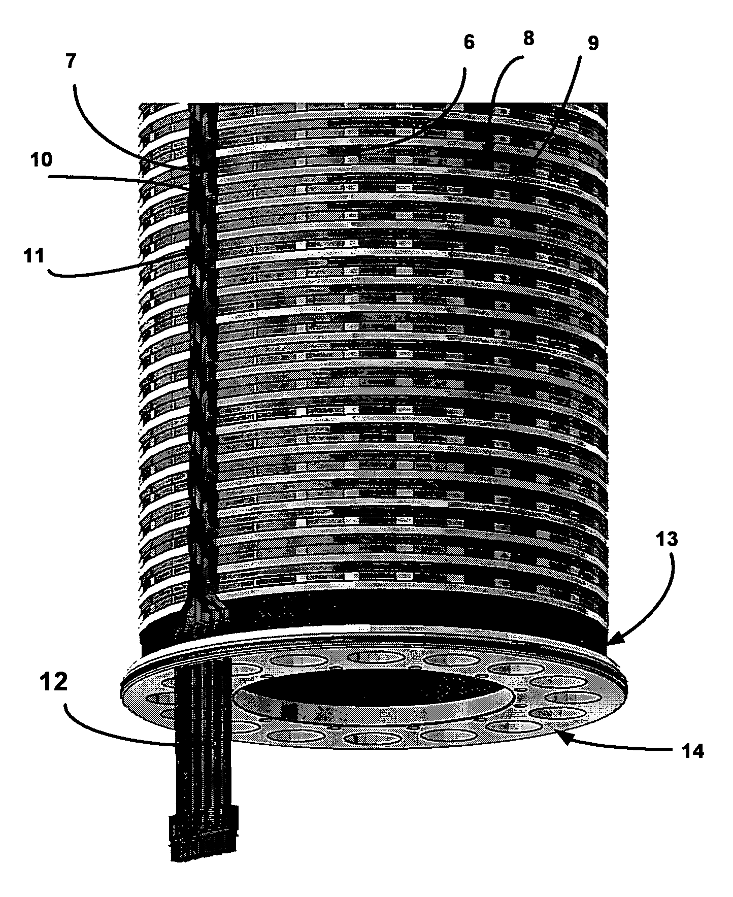
[0058]FIG. 4 shows a typical conductor lamination as first manufactured from a metal sheet, having transverse conducting paths 6, connected by axial conducting paths 7. The axial conducting paths 7 may be considered to be equivalent to the end windings of a conventional coil-wound electrical machine.

[0059]FIG. 5 shows how the cond...


PUM


Abstract

A linear electromagnetic machine is described which comprises first and second substantially cylindrical parts arranged to move relative to each other along a common axis of motion. The first cylindrical part produces a spatially periodic radial magnetic field across an air gap, the magnetic field having a regular alternating polarity along or parallel to the axis of motion. The second cylindrical part comprises a plurality of laminar electrical conductors wrapped into cylindrical form and placed in the air gap to intercept the magnetic field, each of the laminar electrical conductors compromising a regular pattern of electrically conductive paths, the electrically conductive paths of the plurality of laminar electrical conductors being interdigitated together within the air gap. The use of a plurality of laminar electrical conductors having respective electrically conductive paths which are interdigitated (nested) within the air gap provides for a very thin planar structure which enables the air gap to be made small, thereby improving the efficiency of the electromagnetic machine. In more general terms, improvements relating to the design of low-cost cylindrical or elliptical linear electromagnetic machines are described, in which a conventional assembly of wire coils is replaced by a small number of interdigitated metal laminations.

Description

FIELD OF INVENTION[0001]The present invention relates to a linear electromagnetic machine, and more particularly to a linear electromagnetic machine having cylindrical magnetic and electrical parts which move relative to each other to provide linear motion.BACKGROUND OF THE INVENTION[0002]It is known to construct linear electric motors in cylindrical form in which the output is a rod or tube. It is also known to construct such machines with an armature that is not connected externally but is used as a piston for compression, for controlled expansion (the motor being driven in reverse and acting as a generator) or as an inertial mass, the reaction forces being coupled to the load via the stator.[0003]In such machines the magnetic part generally consists of an array of permanent magnets of disc form that produces a radial magnetic field that is spatially-periodic along the axis of the cylinder. The electrical part of such a linear motor consists of a stack of coils or electrical condu...

Claims


Application Information

Patent Timeline
IPC IPC(8): H02K41/03
CPCH02K3/26H02K41/03H02K3/47H02K17/16H02K19/00H02K21/14
Inventor DENNE, PHILLIP RAYMOND MICHAEL
Owner DENNE PHILLIP RAYMOND MICHAEL
Why Eureka
Try Eureka