
Apparatus and method for generating electricity using piezoelectric material

a technology of piezoelectric material and apparatus, which is applied in the direction of mechanical apparatus, generator/motor, machine/engine, etc., can solve the problems of high manufacturing cost and difficulty, and achieve the effects of saving cost, improving manufacturing ease, and increasing electricity

Inactive Publication Date: 2011-02-17
HONG KONG APPLIED SCI & TECH RES INST
View PDF18 Cites 22 Cited by
  • Summary
  • Abstract
  • Description
  • Claims
  • Application Information

AI Technical Summary

Benefits of technology

[0004]The present invention aims to provide an alternative structure for generating electricity from a piezoelectric element. In preferred embodiments the structure may generate more electricity and / or be more robust than prior art designs. Furthermore, some preferred embodiments use one or more simple, non-curved piezoelectric elements; this may lead to cost savings and improved ease of manufacture.
[0009]Preferably at least one spacer is provided between the first elongate member and the piezoelectric element. The spacer may transmit a compressive force to the piezoelectric element when the first elongate member is pushed towards the second elongate member. The spacer may also limit the extent of deformation of the first elongate member. This helps to prevent the elongate member from fracturing.
[0010]Preferably the first elongate member is stiffer than the second elongate member. This improves the tendency of the apparatus to stretch the first elongate member in response to compression of the apparatus pushing the first and second elongate members together.
[0011]In a preferred structure, a third elongate member is provided on an opposite side of the second elongate member to the first elongate member; the third elongate member being joined to the second elongate member at third and fourth points which are spaced apart from each other. This enhances the ability of the apparatus to stretch the second elongate member. Generally the second elongate member has a first face facing the first elongate member and a second face facing the third elongate member. Preferably both the first and second faces are at least partially coated with piezoelectric material. This increases the amount of piezoelectric material (e.g. there may be two or more piezoelectric elements), thus increasing the amount of electricity produced.
[0013]Preferably the piezoelectric element (or elements) is not curved or pre-curved. Instead a simple off-the-shelf block of piezoelectric material (e.g. oblong in shape) or a simple coating may be used. This simplifies the manufacturing process compared to complex custom manufactured pre-curved piezoelectric elements.
[0019]A fifth aspect of the present invention provides an apparatus for generating electricity comprising first, second and third elongate members; wherein said first and third elongate members oppose each other and the second elongate member is provided in between said first and third elongate members; said apparatus being arranged such that when pressure is applied to push said first elongate member towards said third elongate member, the apparatus applies a stretching force to said second elongate member; said second elongate member comprising one or more piezoelectric elements or having one or more piezoelectric elements mounted thereon. This is a simple and convenient structure for producing electricity by deformation of piezoelectric elements when the apparatus is compressed (i.e. when the first elongate member is pushed towards the third elongate member and / or vice versa).

Problems solved by technology

However, it requires a special type of curved piezoelectric element, which is expensive and difficult to manufacture.

Method used


Image

  • Apparatus and method for generating electricity using piezoelectric material
  • Apparatus and method for generating electricity using piezoelectric material
  • Apparatus and method for generating electricity using piezoelectric material

Examples


Embodiment Construction

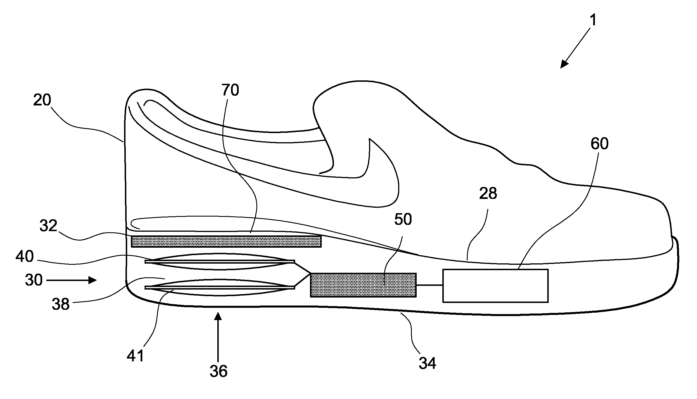
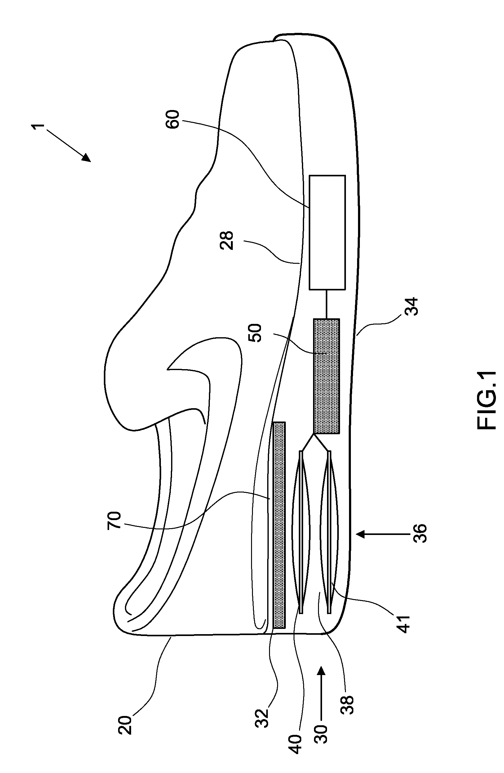
[0047]FIG. 1 shows an article of footwear 1 comprising an upper portion 28 adapted to surround a person's foot and a sole portion 30 adapted to underlie a person's foot and protect it from the ground. The sole has a foot bed surface 28 for contacting a person's foot and a bottom surface 34 for contacting the ground.

[0048]The sole 30 comprises a cavity in which are located a pair of piezoelectric apparatus for generating electricity 40, 41. In alternative embodiments the sole may have only one apparatus for generating electricity 40, or more than two such apparatus. The apparatus 40, 41 are preferably stacked, as shown in FIG. 1, one above the other. The apparatus 40, 41 are located in a portion of the sole just below the heel of the foot (when the footwear is being worn).

[0049]The footwear 1 has one or more electric devices 60 which are fully or partially powered by electricity generating apparatus 40, 41. In this embodiment the electricity generating apparatus 40, 41 are electrical...


PUM


Abstract

An apparatus and method for generating electricity using piezoelectric material. The apparatus comprises a first elongate member and a second elongate member that are joining together at first and second points which are spaced apart from each other. The second elongate member comprises a piezoelectric element, or has a piezoelectric element mounted thereon. When pressure is applied to the first elongate member, the second elongate member is stretched and the stretching force is applied to the piezoelectric element. This generates electricity. A similar arrangement with a third elongate member may be provided on the other side of the second elongate member. The apparatus may be placed in a shoe or underneath a floor, so that the variation in pressure caused by walking may be used in generate electricity.

Description

FIELD OF THE INVENTION[0001]The present invention relates to an apparatus and method for generating electricity using piezoelectric material. It relates in particular, but not exclusively, to an apparatus that is powered by movement of a human body part, e.g. a foot.[0002]It may, for example, be used in the sole of a shoe or under a floor. Then the changes in pressure, caused by a person walking or moving, deform the piezoelectric material causing it to generate electricity.BACKGROUND[0003]U.S. Pat. No. 5,918,502 discloses an article of footwear which has a piezoelectric element in the sole. The piezoelectric element is pre-formed in an arcuate shape. When the wearer of the footwear walks or runs the force of the sole impacting the ground causes the piezoelectric element to deform. This generates electricity. However, it requires a special type of curved piezoelectric element, which is expensive and difficult to manufacture.SUMMARY OF THE INVENTION[0004]The present invention aims to...

Claims


Application Information

Patent Timeline
Patent Type & Authority Applications(United States)
IPC IPC(8): H02N2/18A43B13/18F03G5/00
CPCA43B3/0015H01L41/113H02N2/18A43B3/38H10N30/30
Inventor SHAM, MAN-LUNGGAO, ZIYANGLUI, TUNG CHINGCHUNG, CHANG HWA
Owner HONG KONG APPLIED SCI & TECH RES INST
Features
  • Generate Ideas
  • Intellectual Property
  • Life Sciences
  • Materials
  • Tech Scout
  • Unparalleled Data Quality
  • Higher Quality Content
  • 60% Fewer Hallucinations
Learn More