
Ergonomic control unit for providing a pointing function

a pointing function and ergonomic control technology, applied in the direction of instruments, cathode-ray tube indicators, electric digital data processing, etc., can solve the problems of unsuitable broad control functions, unsuitable for many applications, unsuitable for flat operation, etc., to achieve fine control of the cursor on the screen, easy manipulation, and quick motion of the cursor

Inactive Publication Date: 2011-02-17
BOR IGAL +2
View PDF2 Cites 27 Cited by
  • Summary
  • Abstract
  • Description
  • Claims
  • Application Information

AI Technical Summary

Benefits of technology

[0020]Still another object of the invention is to provide a control unit integrating pressure sensors synchronized with optical sensors so as to enhance pointing functions as well as control and command capabilities. The latter includes enabling selection of control for speed and direction, and resolution of coarse, rough movements; large movements; and fine movements, all in one device.
[0021]Yet another object of the invention is to provide navigational and command functions within a control unit of a remote-control pointing device using simple, inexpensive components.
[0031]The direction of the movement is achieved by the combination of the control provided by one or more pressure sensors which are contacted by a portion of the movable control element (a curved surface—such as a ring, ball, or sphere a flat disk, or any combination of these). Movement is enabled in three dimensions (x, y, and z). The integration of at least one pressure sensor with the movable control element enables the ability to get both coarse, rapid movements and fine movements in one device to serve for many applications where choosing various menu options, such as cursor control and control of navigation, is required.
[0032]Another optional application or feature of the remote-control pointing device is that a switch can be used for selecting the host (such as PC / TV / cellular phone), changing the static speed mode, and / or adjusting the resolution mode—either fine movement or coarse movement. In a preferred embodiment of the present invention, the switch is a simple toggle switch.
[0038]In order to achieve a distinction between slow movements and rapid movements in a movable control element, such as in the case of the ring embodiment of the present invention, the optical sensor, when activated, detects and causes the movement of a cursor to go into a different speed mode. For example, if a quick, jerk-type motion of the ring is initiated, one gets a much quicker motion of the cursor on a display screen for a certain portion of time, and then, when the motion of the ring is slowed, the outcome is finer control of the cursor on the screen.
[0039]The integration of at least one pressure sensor with at least one optical sensor in a system using the control unit of the present invention in a hand-held pointing device enables both coarse and fine movements in one, ergonomic, multi-purpose device which is intuitive to use and easy to manipulate with the fingers for achieving all these different kinds of motions and resolution levels.

Problems solved by technology

A major disadvantage of this type of pointing device is clearly its need to be operated on a flat, fixed surface, usually with a mouse pad.
These solutions, aside from being expensive because they are specialized, primarily rely on interpretation of images generated by broad hand-gestures rather than pointing functions generated by a mouse.
Because more and more remote screens are used at home, at school, and at work it is becoming clear that such a broad control function is unsuitable in many applications where finer control movements are required to carry out these pointing functions.
They are less accurate and harder to use (a user needs to hold the device in the proper orientation in order for the de vice to receive feedback).
Other handheld devices, such as, for example, a Nintendo WII 3D® remote control which needs to be used by a user's hand held up in the air, are not accurate enough for use as a computer mouse and have limited application.
Due to the fact that more and more cellular phones have also moved into providing Internet services using graphic display screens and text features such as SMS, they also require pointing capabilities for navigation and control, but they suffer the disadvantage of having relatively small screens due to the limitations of the size of their housing.
It should be noted that some smaller display screens often require the use of a stylus in conjunction with a touch-screen for finer, precise operation of menu-driven programs, since even activation by use of a mouse tends to be too broad given the physical scale of these devices.
Although the use of remote screens in many applications and across many platforms has increased many times over as a result of rapid product development, the state of the art of remote control pointing devices has not kept pace with it.
For example, in many cellular applications, fine movement may be required, but cursor controls for cellular devices generally lack fine movement suitable for use with their small-sized screens.
Use of a stylus and or light finger pressure on touch-type screens is an inefficient and inaccurate mode of operation for making fine movements for a pointer device.
This is problematic when, for example, fine movements might be required, such as for navigating within web pages or playing online games with speed and dexterity.
Most hand-held remote-control pointing devices for operating electronic devices, such as TV and entertainment systems, air conditioners, heating units, garage and door openers, and the like each require an expensive, specialized unit with finger-operated push-buttons, sometimes configured in different arrays and provided with a variety of specialized symbols and often these are not intuitive.
Aside from the expense involved either in the manufacture or acquisition of each new pointing device for every new, remote-controlled appliance purchased, a user must spend time learning the new sophisticated system of buttons and their often esoteric symbols for operation.
Furthermore, the fact that some pointing devices need to be operated in conjunction with a fixed, planar surface, limits their usefulness for other applications.
Prior art, hand-held, remote-control pointing devices all suffer from one or more of the disadvantages described above.

Method used


Image

  • Ergonomic control unit for providing a pointing function
  • Ergonomic control unit for providing a pointing function
  • Ergonomic control unit for providing a pointing function

Examples


Embodiment Construction

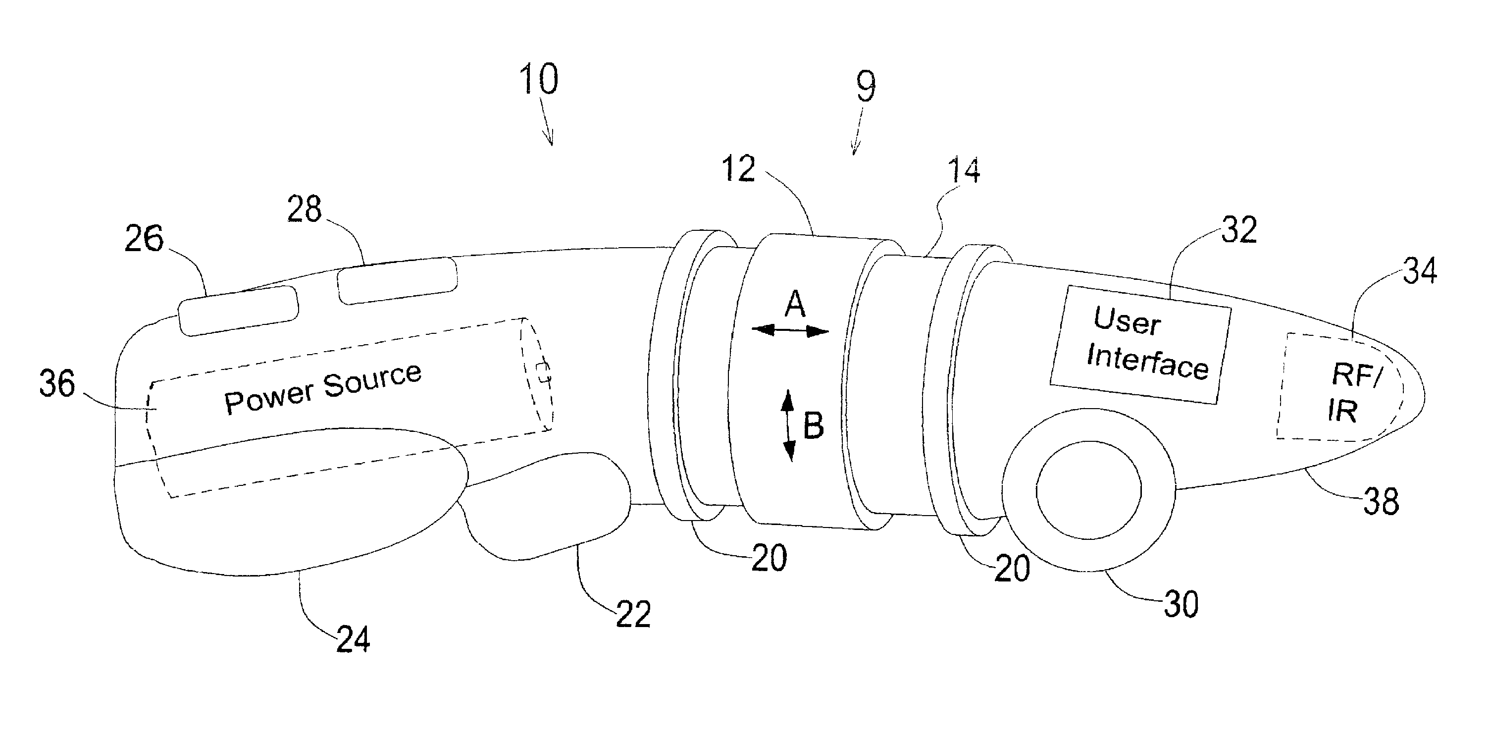
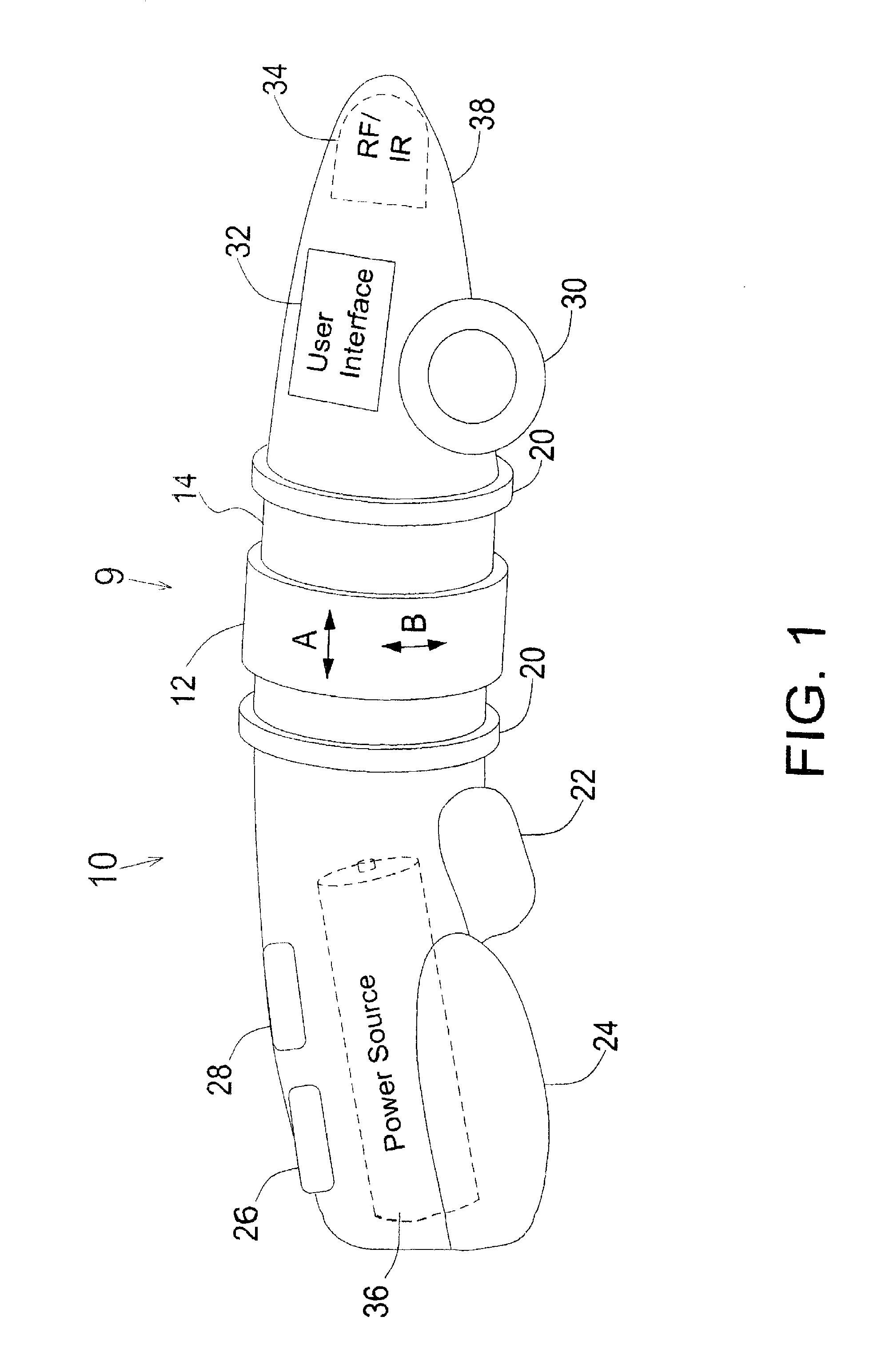
[0057]Referring now to FIG. 1, there is shown a general view of an exemplary embodiment of the present invention incorporated within a pointing device.

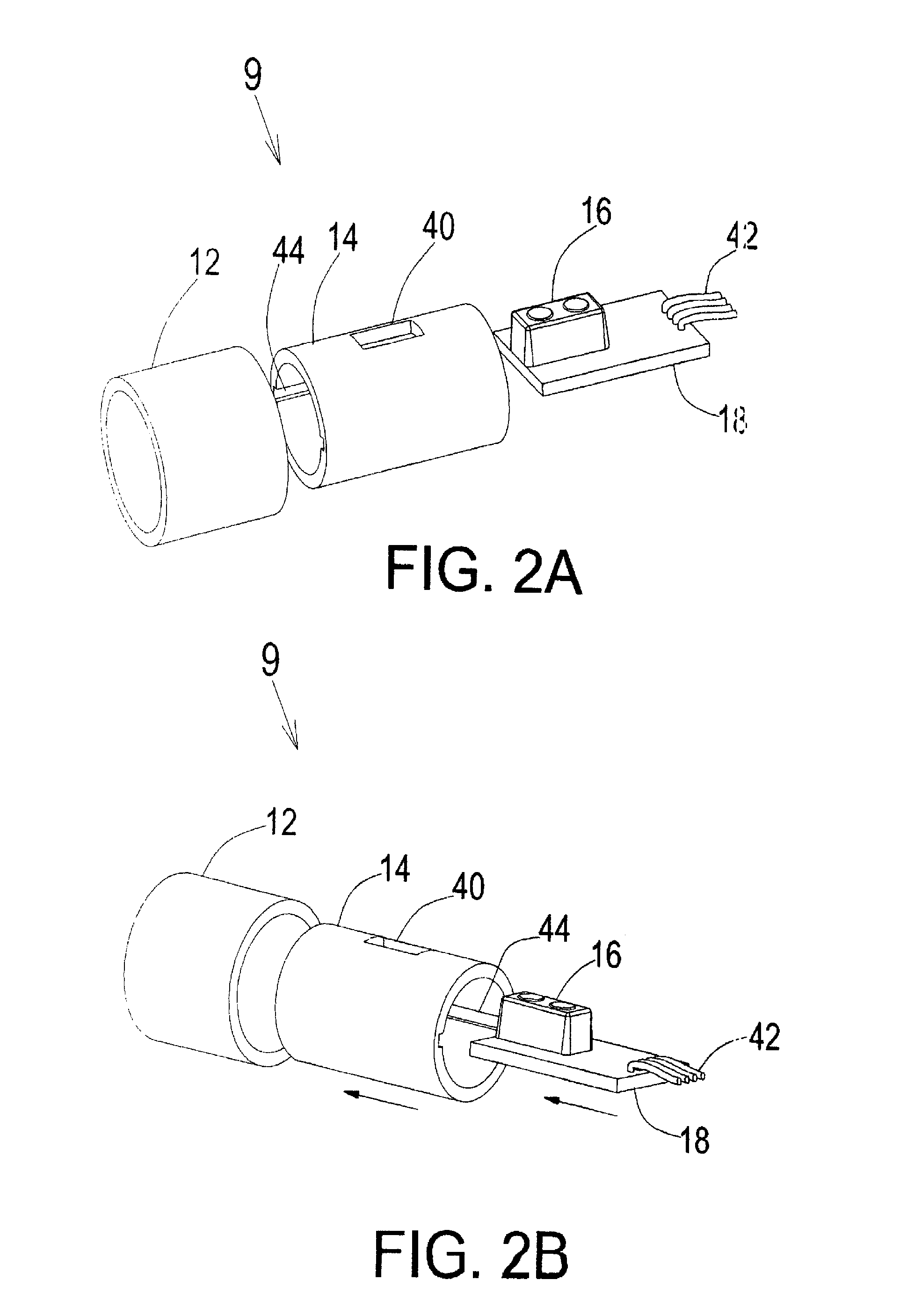
[0058]The hand-held, remote-control pointing device 10 incorporates a control unit 9, comprising a ring element 12 which is rotatable (arrow B) and slidable (arrow A) about a stationary cylindrical tube 14 anchored within the body 38 of pointing device 10. There is provided at least one, internally mounted, optical sensor 16 (see FIGS. 2A / 2B for details). Two pressure sensors 20 are disposed, one at each limit of the sliding motion (indicated by arrow A) of ring element 12. Optionally, ring element 12 has an indentation formed in its outer surface to accommodate a human thumb or any other finger that is capable of manipulating it to rotate or slide.

[0059]Each pressure sensor 20 limits the axial movement of ring element 12 along the axis of device 10 in either direction (as shown by arrow A). These pressure sensors 20 provide control f...


PUM


Abstract

A control unit disposed in a remote-control pointing device for providing a control and pointing function. The control unit comprises a stationary element, a movable control element with a reflective surface disposed proximate to the stationary element, at least one optical sensor fixedly disposed in close proximity to the movable control element, and at least one pressure sensor. When the optical sensor is activated by movement of the movable control element and when the movable control element is put into pressure contact with the pressure sensor, location and pressure contact data, respectively, are collected by the control unit enabling control and pointing functions associated with the pointing device without the need for an external, stationary reference surface.

Description

FIELD OF THE INVENTION[0001]The present invention generally relates to the field of portable, hand-held, remote-control pointing devices for pointing and generating information pertaining to a target location, and more particularly, to an ergonomic control unit incorporated in such a remote-control pointing device for providing a multi-application pointing function without the need for a stationary, external reference surface.BACKGROUND OF THE INVENTION[0002]Existing hand-held, remote-control, pointing devices (hereinafter, “pointing devices”)—such as a computer mouse for moving a cursor on a display screen or for performing specific computer operations and a remote-control for operating and guiding electro-mechanical equipment or devices—are used not only for pointing to a target location, but optionally for generating information pertaining to the target location and for controlling various modes of operation.[0003]These kinds of pointing devices are generally equipped with optica...

Claims


Application Information

Patent Timeline
IPC IPC(8): G06F3/033
CPCG06F3/033G06F3/0338G06F3/0362G06F3/03548G06F3/0354
Inventor BOR, IGALOR, TALBOR, NECHEMIA
Owner BOR IGAL
Learn More