Method and System for Compensating Imaging Defect in Image Forming Apparatus

a technology compensating imaging defect, which is applied in the field of image forming apparatus, can solve the problems of reducing the quality of images, and affecting the quality of images

Inactive Publication Date: 2011-02-17
LEXMARK INT INC
View PDF20 Cites 4 Cited by
  • Summary
  • Abstract
  • Description
  • Claims
  • Application Information

AI Technical Summary

Benefits of technology

[0012]In view of the foregoing disadvantages inherent in the prior art, the general purpose of the present disclosure is to provide a method for compensating an imaging defect in an image forming apparatus, to include all the advantages of the prior art, and to overcome the drawbacks inherent therein.

Problems solved by technology

During operation of an image forming apparatus, such as a laser printer, a copying machine, and a multifunctional peripheral, various imaging defects may appear in images rendered by the image forming apparatus.
These imaging defects considerably reduce the quality of the images that might leave users of the image forming apparatus unsatisfied with the quality of the image.
The clouding defect primarily occurs due to non-uniformity in thickness of a Photoconductor (PC) drum of the image forming apparatus, and more specifically, on a charge transport layer (CTL) of the PC drum.
Moreover, the clouding defect may also occur due to wear and tear of the CTL of the PC drum after a prolonged usage of the PC drum, and due to environmental conditions existing in a place, where the image forming apparatus is operated.
In addition to directly reducing the quality of the images, such imaging defects may cause various indirect effects.
One such indirect effect may be wastage of resources during manufacturing of the image forming apparatus.
Discarding the PC drums clearly wastes resources.
However, the use of the expensive fabrication process results in an increase of manufacturing costs for the manufacturers.
Moreover, the clouding defect intensifies with time.
Once the clouding defect becomes sufficiently severe, the typical solution is to simply replace the PC drum of the image forming apparatus, which may prove very expensive for the user of the image forming apparatus.

Method used


Image

  • Method and System for Compensating Imaging Defect in Image Forming Apparatus
  • Method and System for Compensating Imaging Defect in Image Forming Apparatus
  • Method and System for Compensating Imaging Defect in Image Forming Apparatus

Examples


example

[0073]In the following example, the method of the present disclosure, such as method 100, was investigated in an image forming apparatus for compensating an imaging defect therein. Such an investigation will now be described with reference to FIGS. 8a, 8b, 9a, 9b, and 10.

[0074]FIG. 8a depicts a full-page print 800 by the image forming apparatus. Full page print 800 represents an original printing by the image forming apparatus including the imaging defects. In this investigation, full-page print 800 is of constant gray level, and has average lightness (L*) of about 50 L*. It will be apparent to a person skilled in the art that the term ‘average lightness’ mentioned herein refers to a perception of darkness of an image as detected by a human eye or measured by an apparatus, such as a reflection densitometer. Accordingly, the average lightness of 50 L* refers to a perceived darkness of about 50 percent by the human eye or the reflection densitometer.

[0075]As depicted in FIG. 8a, full-...


PUM


Abstract

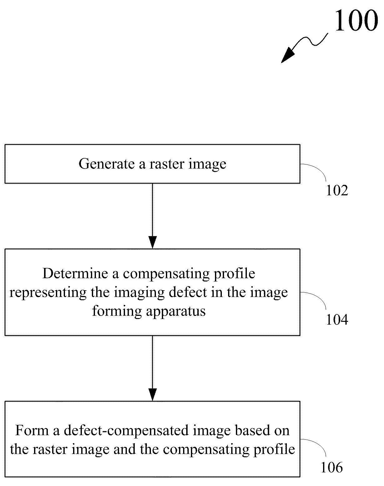
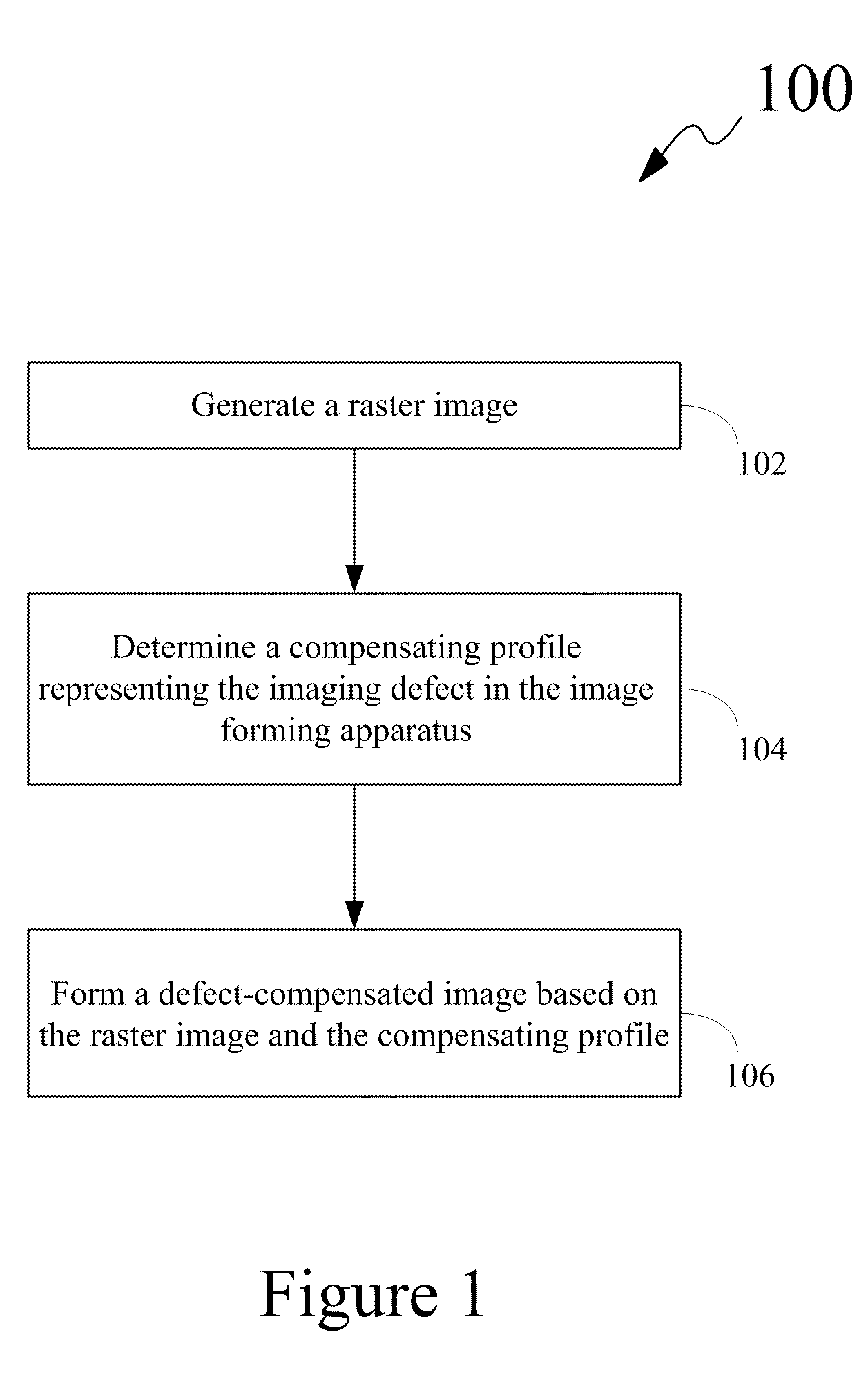
Disclosed is a method for compensating an imaging defect in an image forming apparatus. The method includes generating a raster image. Further, the method includes determining a compensating profile representing the imaging defect in the image forming apparatus. Furthermore, the method includes forming a defect-compensated image based on the raster image and the compensating profile. Also, disclosed is the image forming apparatus capable of compensating the imaging defect thereof.

Description

CROSS REFERENCES TO RELATED APPLICATIONS[0001]None.STATEMENT REGARDING FEDERALLY SPONSORED RESEARCH OR DEVELOPMENT[0002]None.REFERENCE TO SEQUENTIAL LISTING, ETC.[0003]None.BACKGROUND[0004]1. Field of the Disclosure[0005]The present disclosure relates generally to image forming apparatuses, and more particularly, to compensating imaging defects in the image forming apparatuses.[0006]2. Description of the Related Art[0007]During operation of an image forming apparatus, such as a laser printer, a copying machine, and a multifunctional peripheral, various imaging defects may appear in images rendered by the image forming apparatus. These imaging defects considerably reduce the quality of the images that might leave users of the image forming apparatus unsatisfied with the quality of the image.[0008]One such imaging defect is known as a ‘clouding defect.’ The clouding defect is recognized by the appearance of a repeating ‘clouding pattern’ in the images rendered by the image forming app...

Claims


Application Information

Patent Timeline
Patent Type & Authority Applications(United States)
IPC IPC(8): G06K15/02
CPCH04N1/40025
Inventor COOPER, BRIAN EDWARDEID, AHMED HAMAD MOHAMEDWEN, JIAN
Owner LEXMARK INT INC
Why Eureka
Try Eureka