Compact Mobile Cargo Scanning System

a cargo scanning and mobile technology, applied in material analysis, material analysis using wave/particle radiation, instruments, etc., can solve the problems of inability to achieve typical scenarios, inability to easily modify, and insufficient spa

Inactive Publication Date: 2011-02-17
RAPISCAN SYST INC (US)
View PDF99 Cites 95 Cited by
  • Summary
  • Abstract
  • Description
  • Claims
  • Application Information

AI Technical Summary

Benefits of technology

[0025]In another embodiment, the inspection system comprises a vehicle having a first axle proximate to a front of said vehicle and one or more rear axles proximate to a back of said vehicle wherein a first area is bounded by the rear axle extending to the front of said vehicle and a second area is bounded by the rear axle extending to the back of said vehicle; a radiological source; a boom, having a weight, rotatably attached to said vehicle wherein said boom comprises a first vertical section, a second vertical section and a horizontal section and wherein said weight is positioned to substantially act over said first area and not said second area, wherein said system weighs 15,000 kg or less.
[0026]The system is capable of achieving radiological penetration of at least 30 mm of steel. When fully deployed, the boom defines ...

Problems solved by technology

However, these scenarios are not typically feasible.
Space is generally in substantial demand and short supply.
Existing ports operate under a routine that is not easily modified without causing disruption to the entire infrastructure of the port.
With limited space and a need to expand, finding suitable space to accommodate additional inspection facilities along the normal process route remains difficult.
Additionally, selected locations are not necessarily permanent enough for port operators to commit to the long term installation of inspection equipment.
In either case, the building footprint is significant depending upon the size of cargo containers to be inspected.
This limits the flexibility of dismantling the entire system for optimum portability and adjustable deployment to accommodate a wide array of different sized cargo, shipments, vehicles, and other containers.
As a result these systems can be complicated to deploy and pose several disadvantages and constraints.
For example, in a moving-scan-engine system the movement of the source and detector, relative to a stationary object, may cause lateral twist and lift and fall of the detector or source, due to movement of the scanner over uneven ground, inducing distortions in the scanned images and faster wear and tear of the scanner system.
Such systems that require a detector-mounted boom to unfold d...

Method used


Image

  • Compact Mobile Cargo Scanning System
  • Compact Mobile Cargo Scanning System
  • Compact Mobile Cargo Scanning System

Examples


Embodiment Construction

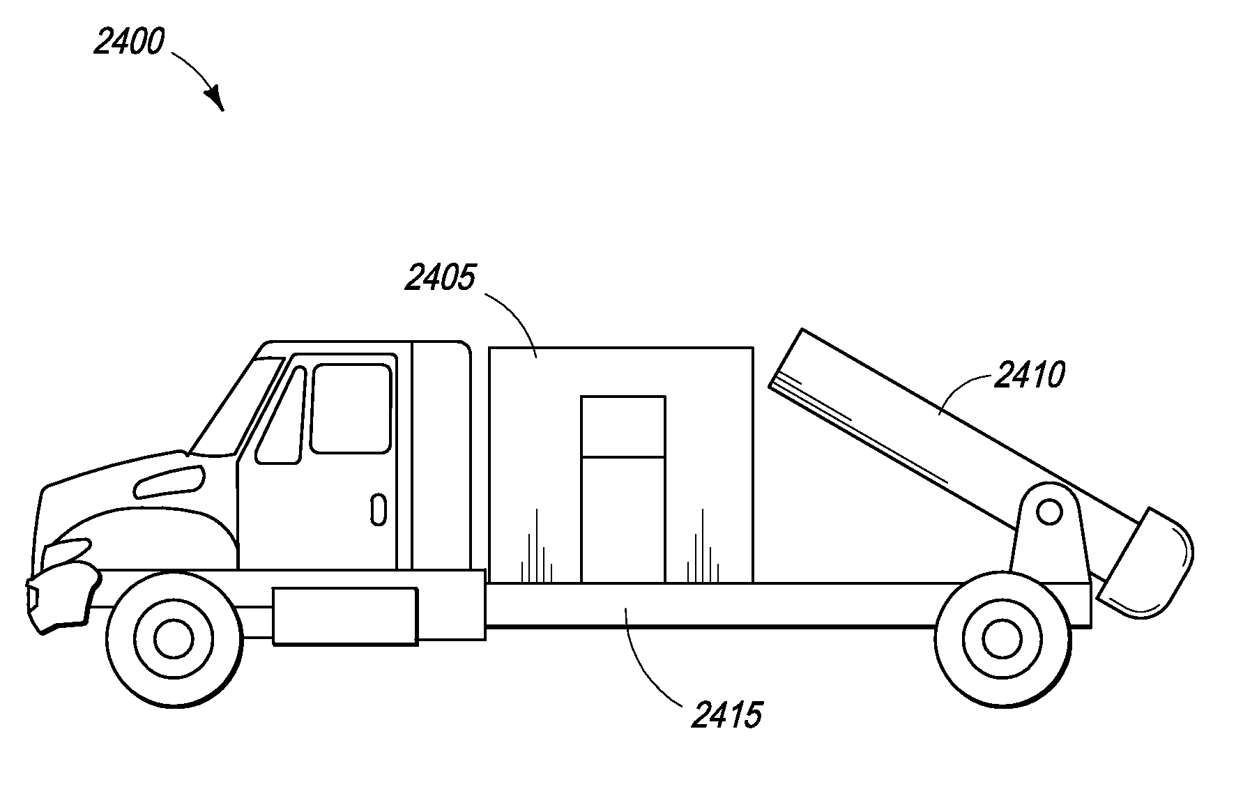
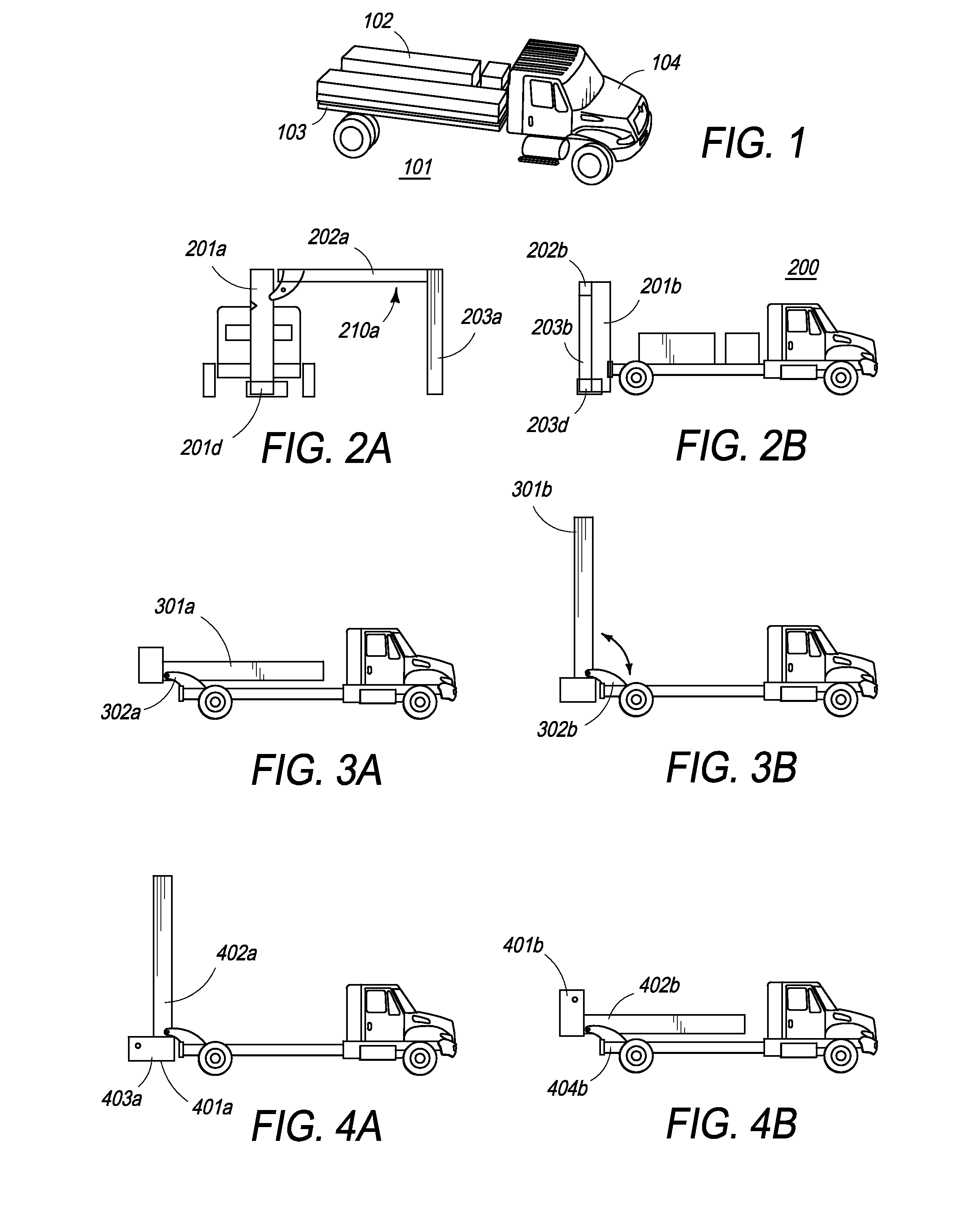
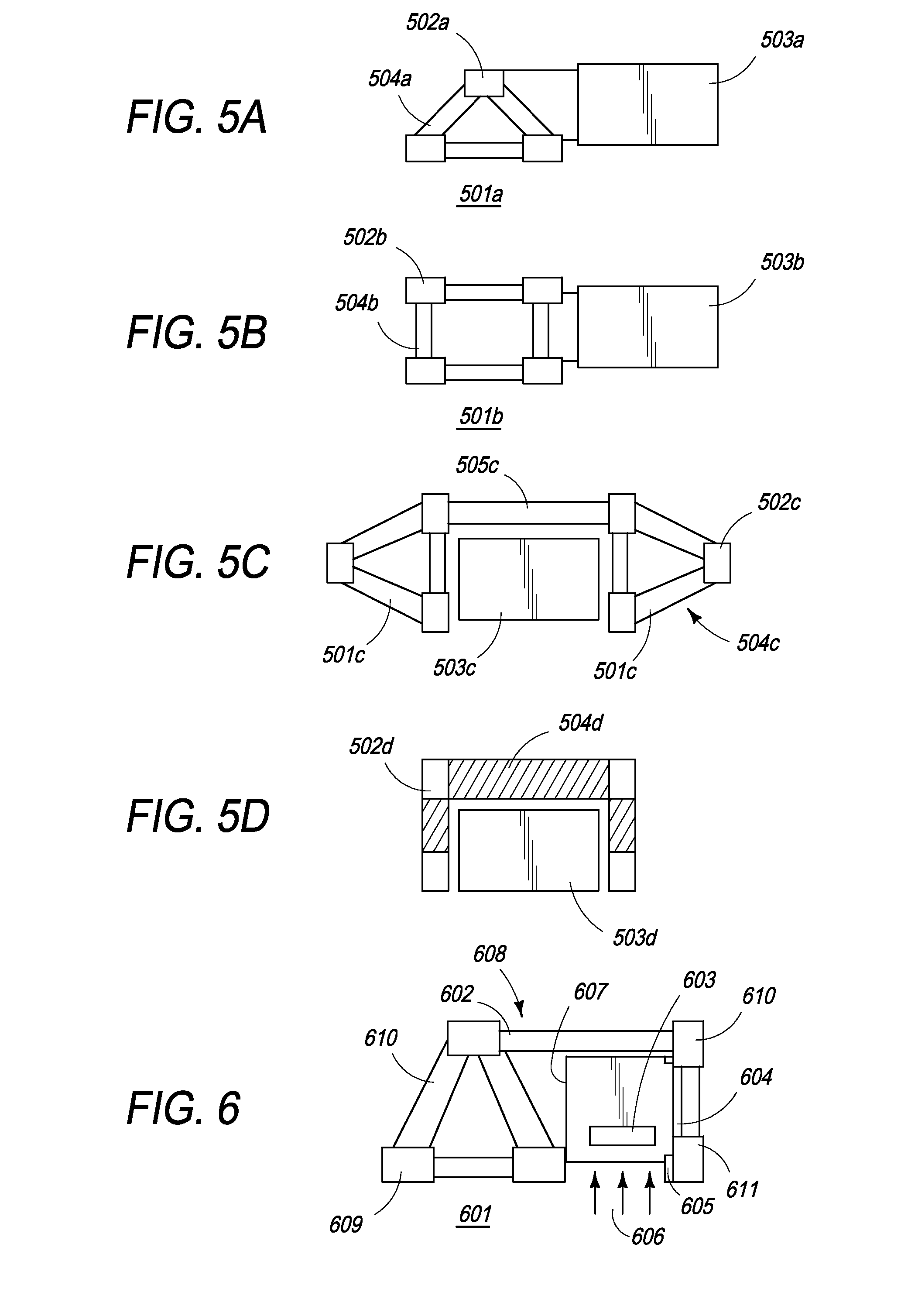
[0087]The present invention is directed towards a portable inspection system for generating an image representation of target objects using a radiation source, comprising a mobile vehicle; a detector array physically attached to a single, movable boom having a proximal end and a distal end and at least one source of radiation wherein the radiation source is fixedly attached to the proximal end of the boom and adjustable to a desired scanning height. The image is generated by introducing target objects between the radiation source and the detector array, thereby exposing objects to radiation and subsequently detecting the radiation. The boom can be unfolded from a first stowed configuration to a second deployed and operational configuration.

[0088]The system of the present invention is advantageous in that it provides a highly compact stowed configuration and has a low height, such that the highest part of the boom does not exceed the height of the drive cab, among other benefits. The...


PUM


Abstract

The present invention is a self-contained mobile inspection system and method and, more specifically, improved methods and systems for detecting materials concealed within a wide variety of receptacles and/or cargo containers. In particular, the present invention is an improved method and system with a novel boom structure that reduces the weight of the boom. The single, light-weight boom of the inspection system is relatively compact in a stowed configuration and has a low height and center of gravity lending to greater maneuverability.

Description

CROSS-REFERENCE[0001]The present invention relies on U.S. Provisional Patent Application No. 61 / 180,471, filed on May 22, 2009, for priority.[0002]The present invention is a continuation-in-part of U.S. patent application Ser. No. 12 / 339,591, entitled Rotatable Boom Cargo Scanning System, filed on Dec. 19, 2008, which is a continuation-in-part of U.S. patent application Ser. No. 11 / 948,814, entitled, “Single Boom Cargo Scanning System”, filed on Nov. 30, 2007, which is a continuation of U.S. Pat. No. 7,322,745, entitled, “Single Boom Cargo Scanning System”, filed on Aug. 9, 2004, which relies on, for priority, U.S. Provisional Patent Application No. 60 / 493,935, filed on Aug. 8, 2003 and is a continuation-in-part of U.S. patent application Ser. No. 10 / 201,543, entitled “Self-Contained Portable Inspection System and Method”, filed on Jul. 23, 2002 and now U.S. Pat. No. 6,843,599. The '591 application further relies on U.S. Provisional Application No. 61 / 014,814, filed on Dec. 19, 2007...

Claims


Application Information

Patent Timeline
IPC IPC(8): G01N23/04
CPCG01N2223/639H05G1/02G01V5/0066G01V5/0016
Inventor MORTON, EDWARD JAMESBALDWIN, FRANCISKOTOWSKI, ANDREAS F.
Owner RAPISCAN SYST INC (US)
Why Eureka
Try Eureka