Cartridge, and electrophotographic image forming apparatus which uses cartridge
Inactive Publication Date: 2011-02-17
CANON KK
View PDF28 Cites 127 Cited by
Summary
Abstract
Description
Claims
Application Information
AI Technical Summary
This helps you quickly interpret patents by identifying the three key elements:
Problems solved by technology
Method used
Benefits of technology
Benefits of technology
[0012]Thus, one of the primary objects of the present invention is to provide a cartridge which does not suffer from the above-described problems of the conventional technologies, and also, an electrophotographic image forming apparatus compatible with a cartridge in accordance with the present invention.
[0013]Another object of the present invention is to provide a cartridge, the development roller of which smoothly rotates even if the cartridge is mounted in an electrophotographic image forming apparatus which is not provided with a mechanism for moving the main assembly portion of the coupling for transmitting rotational force to the development, in the direction parallel to the axial line of the coupling, and also, to provide an electrophotographic image forming apparatus in which the above described cartridge is removably mountable.
[0014]A further object of the present invention is to provide a cartridge which can be removed from the main assembly of an electrophotographic image forming apparatus, which is provided with a cartridge driving shaft, in the direction which is practically perpendicular to the axial line of the cartridge driving shaft, and also, an electrophotographic image forming apparatus in which the cartridge described above is removably mountable.
Problems solved by technology
In the case of this structural arrangement, however, the portion through which driving force is transmitted from the main assembly to the cartridge is the interface (point of meshing) between the driving force transmitting gear of the main assembly, and the driving force receiving gear of the cartridge, making it difficult to prevent the problem that the development roller fluctuates in its rotational speed.
Method used
Image
Click on the blue label to locate the original text in one second.
Reading with bidirectional positioning of images and text.
Examples
embodiment 1
[0103]To begin with, the present invention will be described with reference to one of the examples of a development cartridge compatible with the present invention.
[0104]It should be noted here that a development cartridge is an example of a process cartridge.
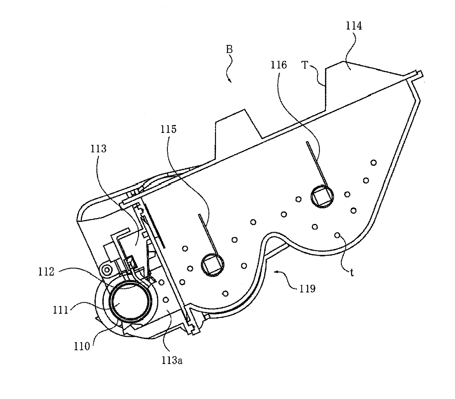
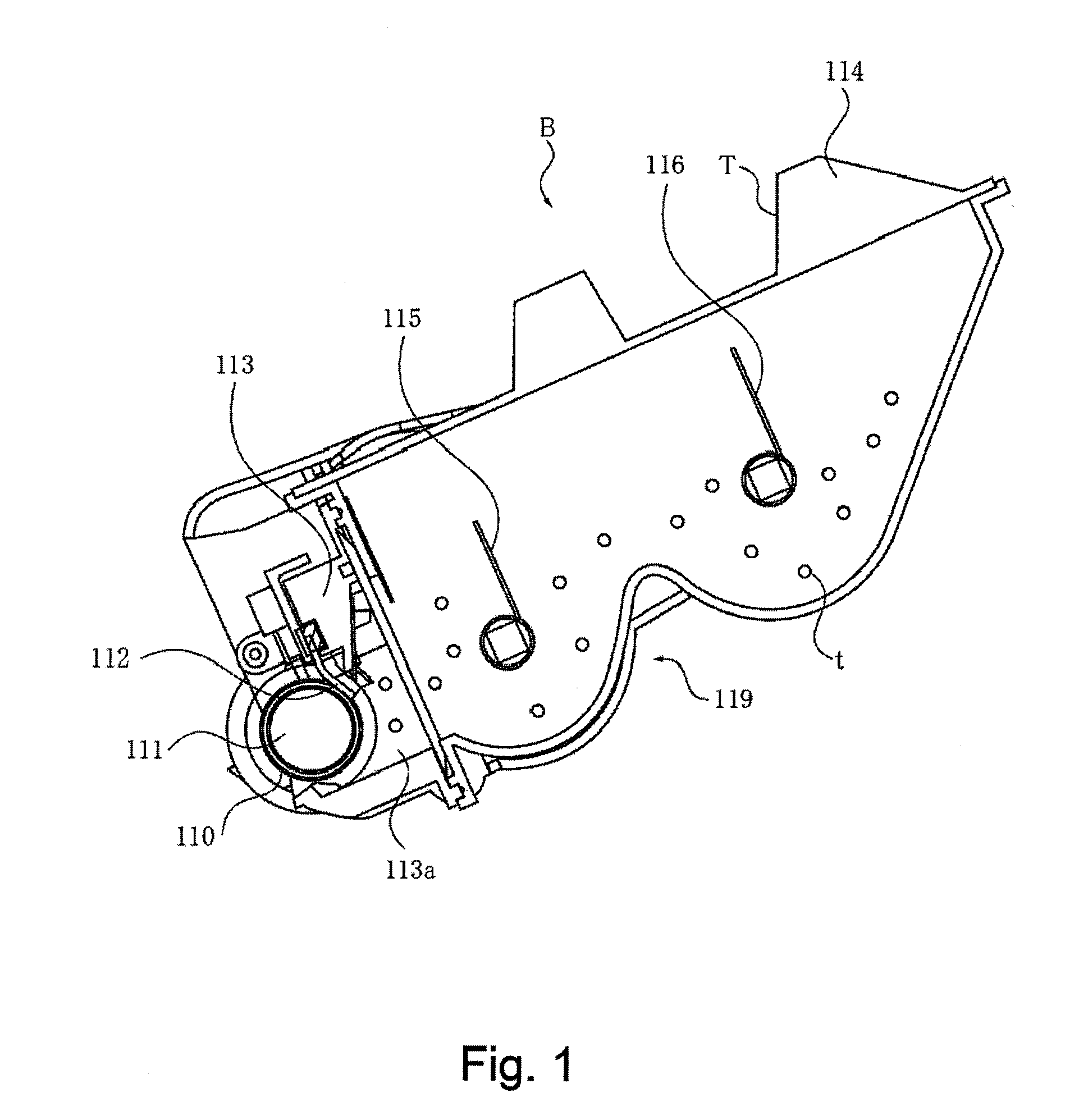
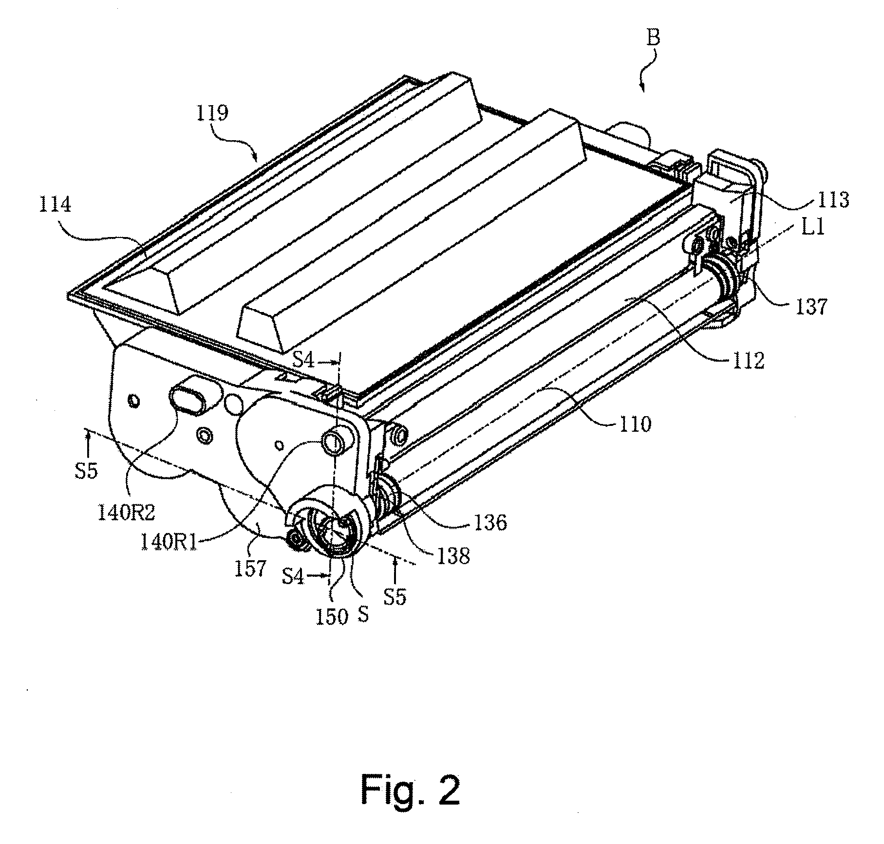
[0105]First, referring to FIGS. 1-4, a development cartridge B (which hereafter will be referred to simply as cartridge), which is one of the embodiments of the present invention, will be described. FIG. 1 is a sectional view of the cartridge B. FIGS. 2 and 3 are perspective views of the cartridge B. Further, FIG. 4 is a sectional view of the main assembly A of an electrophotographic image forming apparatus (which hereafter will be referred to simply as main assembly A).
[0106]The cartridge B is attachable to, or detachable from, the main assembly A by a user.
[0107]Referring to FIGS. 1-4, the cartridge B has a development roller 110. Referring to FIG. 4, the cartridge B is mounted in the m...
embodiment 2
[0314]Referring to FIGS. 32-36, the second embodiment of the present invention will be described. For example, the coupling of the first modified example is taken. However, the present embodiment is applicable also to the coupling of the first embodiment, for example. As for the structure of the coupling, the proper structure is selected by the person skilled in the art.
[0315]In the description of this embodiment, the same reference numerals as in Embodiment 1 are assigned to the elements having the corresponding functions in this embodiment, and the detailed description thereof is omitted for simplicity The same applies all the subsequent embodiments.
[0316]The present embodiment may be applied only for the case of dismounting the cartridge B from the main assembly A.
[0317]In the case of stopping the drive shaft 180 by the controlling operations of the main assembly A, the drive shaft 180 is stopped in the predetermined phase (A predetermined orientation of the pin 182). The phase o...
embodiment 3
[0341]Embodiment 3 to which the present invention is applied will be described with reference to FIGS. 37 to 41. A structure of the coupling is as described in Embodiment 2.
[0342]FIG. 37 is a sectional view showing a state in which a door of the apparatus main assembly A2 is opened. FIG. 38 is perspective view showing a mounting guide in the state in which the door of the apparatus main assembly 42 is opened. FIG. 39 is an enlarged view of a driving-side surface of the cartridge. FIG. 40 is a perspective view as seen from the driving side of the cartridge. FIG. 41 is a schematic view for illustrating two states including a state immediately before the cartridge is inserted into the apparatus main assembly and a state after the cartridge is mounted at a predetermined position in a single drawing for simplicity.
[0343]In this embodiment, the case of mounting the cartridge toward a vertically lower portion, e.g., as a clamshell type image forming apparatus will be described. A represent...
PUM
Abstract
A cartridge for use with a main assembly of an electrophotographic image forming apparatus, the main assembly including a driving shaft having a rotational force applying portion, wherein the cartridge is dismountable from the main assembly in a direction substantially perpendicular to an axial direction of the driving shaft, the cartridge including i) a developing roller for developing an electrostatic latent image formed on an electrophotographic photosensitive drum, the developing roller being rotatable about an axis thereof; and ii) a coupling member engageable with the rotational force applying portion to receive a rotational force for rotating the developing roller, the coupling member being capable of taking a rotational force transmitting angular position for transmitting the rotational force for rotating the developing roller to the developing roller and a disengaging angular position in which the coupling member is inclined away from the rotational force transmitting angular position, wherein when the cartridge is dismounted from the main assembly of the electrophotographic image forming apparatus in a direction substantially perpendicular to the axis of the developing roller, the coupling member moves from the rotational force transmitting angular position to the disengaging angular position.
Description
TECHNICAL FIELD[0001]The present invention relates to a cartridge, and an electrophotographic image forming apparatus in which a cartridge is removably mountable.[0002]Here, an electrophotographic image forming apparatus means an electrophotographic copyingmachine, an electrophotographic printer (laser beam printer, LED printer, etc.), and the like.[0003]A cartridge means a development cartridge as well as a process cartridge. Here, a development cartridge means a cartridge which has a development roller for developing an electrostatic latent image formed on an electrophotographic photosensitive member, and which is removably mountable in the main assembly of an electrophotographic image forming apparatus. Some electrophotographic image forming apparatuses are structured so that the electrophotographic photosensitive member is a part of the main assembly of the image forming apparatus, whereas some electrophotographic image forming apparatuses are structured so that they employ a p...
Claims
Application Information
Patent Timeline
Application Date:The date an application was filed.
Publication Date:The date a patent or application was officially published.
First Publication Date:The earliest publication date of a patent with the same application number.
Issue Date:Publication date of the patent grant document.
PCT Entry Date:The Entry date of PCT National Phase.
Estimated Expiry Date:The statutory expiry date of a patent right according to the Patent Law, and it is the longest term of protection that the patent right can achieve without the termination of the patent right due to other reasons(Term extension factor has been taken into account ).
Invalid Date:Actual expiry date is based on effective date or publication date of legal transaction data of invalid patent.

