
Method Of Controlling The Pitch Velocity Of A Wind Turbine Blade And Control System Therefore

a technology of wind turbine blade and control system, which is applied in adaptive control, non-positive displacement fluid engines, liquid fuel engine components, etc., can solve the problem of wind turbine including the rotor system being less robust than normal

Active Publication Date: 2011-02-17
VESTAS WIND SYST AS
View PDF6 Cites 12 Cited by
  • Summary
  • Abstract
  • Description
  • Claims
  • Application Information

AI Technical Summary

Benefits of technology

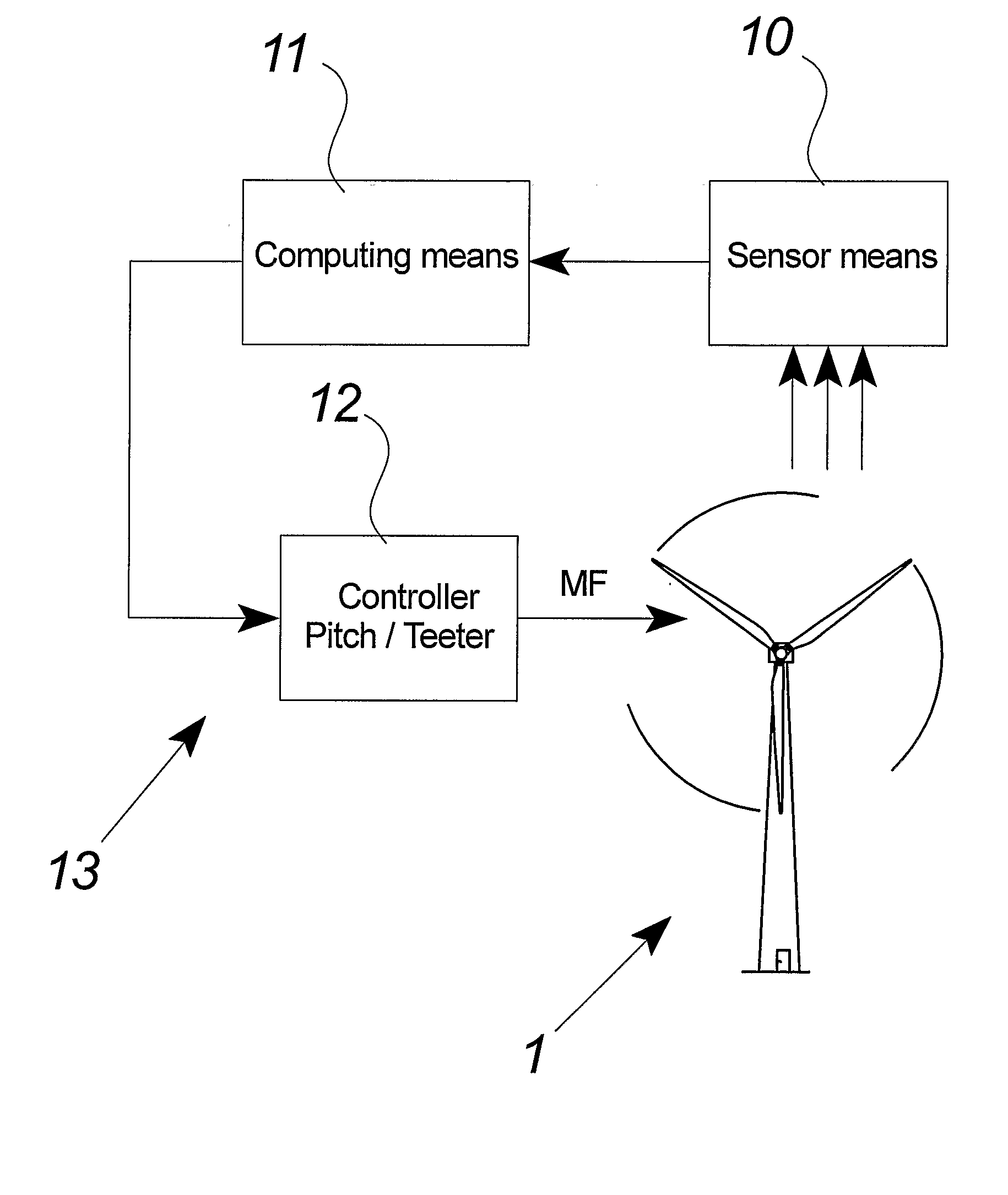
[0011]Hereby is established a method without the above-mentioned disadvantages of the prior art. Especially, it is advantageous that the method allows the rotor of the wind turbine to be optimally and actively stopped in response to feedback values of the wind turbine and / or the surroundings of the wind turbine. The active control of the wind turbine blades allows the wind turbine to be stopped quickly without exposing the wind turbine to excessive forces i.e. an optimizing between time and forces in stopping the rotor.
[0035]In aspects of the invention, said at least one wind turbine blade is part of a wind turbine with two or three blades and said pitch actuator system includes electric motors e.g. electric stepper motors controlling the pitch angle of said at least one wind turbine blade. The use of electric motors allows the creation of precise and swiftly reacting pitch actuator systems which is advantageous in connection with the present invention.

Problems solved by technology

Consequently, the method allows the wind turbine including the rotor system to be dimensioned less robust than normal as the wind turbine will not undergo considerable and potentially harmful forces during the optimal and swift stopping process.

Method used


Image

  • Method Of Controlling The Pitch Velocity Of A Wind Turbine Blade And Control System Therefore
  • Method Of Controlling The Pitch Velocity Of A Wind Turbine Blade And Control System Therefore
  • Method Of Controlling The Pitch Velocity Of A Wind Turbine Blade And Control System Therefore

Examples


Embodiment Construction

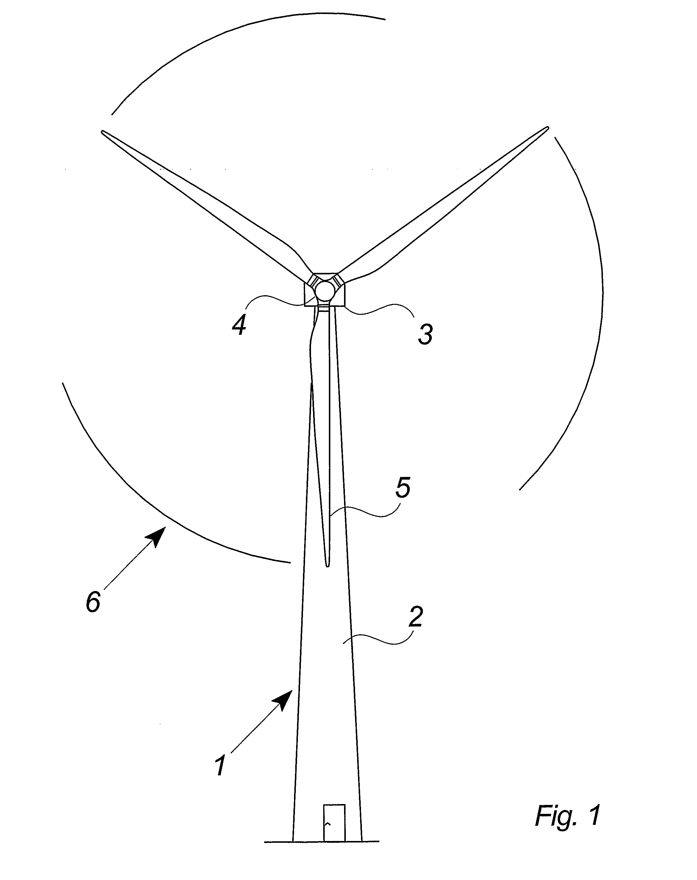
[0047]FIG. 1 illustrates a modern wind turbine 1 with a tower 2 and a wind turbine nacelle 3 positioned on top of the tower. The blades 5 of the wind turbine rotor are connected to the nacelle through the low speed shaft which extends out of the nacelle front.

[0048]As illustrated in the figure, wind over a certain level will activate the rotor and allow it to rotate in a perpendicular direction to the wind. The rotation movement is converted to electric power which usually is supplied to the transmission grid as will be known by skilled persons within the area.

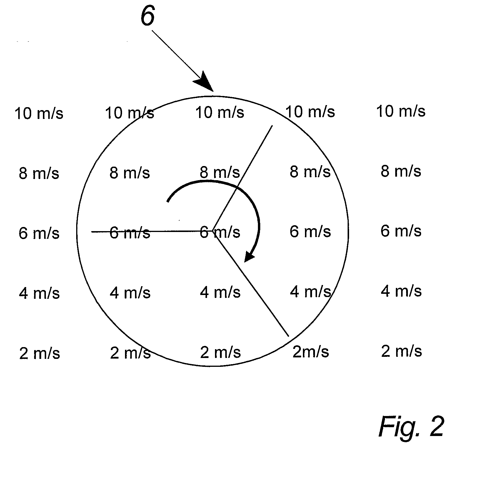
[0049]FIG. 2 illustrates the distribution of the wind forces which the large rotor 6 faces e.g. strong wind forces at the top of the rotor (e.g. 10 meter per second) and decreasing wind forces (e.g. from 8 to 2 meter per second) toward the bottom of the rotor. The rotor faced distribution of wind forces may result in a very strong moment on the wind turbine in which the wind forces literally try to break off the nacelle from t...


PUM


Abstract

A method of controlling at least one wind turbine blade during the stopping process of the rotor in a wind turbine system is disclosed. The method optimizes the control velocity of the process in response to one or more feedback values of the system and / or one or more feedback values from the surroundings of the system by altering the angular pitch velocity from 10° / sec during the initial stage of the stopping process to 5° / sec at the final stage of the stopping process. A control system and a wind turbine as well as use hereof are also disclosed.

Description

CROSS-REFERENCE TO RELATED APPLICATIONS[0001]This application is a continuation of pending U.S. patent application Ser. No. 11 / 658,385 filed Sep. 25, 2007, which is the National Stage of International patent application PCT / DK2004 / 000512 filed on Jul. 23, 2004 which designated the United States. The content of all prior applications is incorporated herein by reference.FIELD OF THE INVENTION[0002]The invention relates to method of controlling at least one wind turbine blade during stopping process of the rotor in a wind turbine system, control system, wind turbine and use hereof.BACKGROUND OF THE INVENTION[0003]The stopping process may be initiated in order to avoid overload situations for a wind turbine e.g. if the electric generator of the wind turbine suddenly is disconnected the utility grid.[0004]Previously, wind turbine blades of a wind turbine have been controlled during a stopping process by using pre-established values for the pitch velocity until the blades are fully pitche...

Claims


Application Information

Patent Timeline
Patent Type & Authority Applications(United States)
IPC IPC(8): F03D7/04F03D11/00G06F1/28F03D7/02
CPCF03D7/0224F03D7/024F03D7/0264F05B2270/1011F05B2270/107Y02E10/723F05B2270/309F05B2270/32F05B2270/321F05B2270/326F05B2270/328F05B2270/1071Y02E10/72
Inventor JEPPESEN, OLE MOLGAARDBENGTSON, JOHNHANSEN, TORBEN MOLLER
Owner VESTAS WIND SYST AS
Learn More