Working vehicle engine output control system and method

a technology for working vehicles and control systems, applied in the direction of machines/engines, vehicle sub-unit features, instruments, etc., can solve the problems of excessive torque input into the transmission, the work vehicle is easy to overheat, and the output of the engine is reduced. , to achieve the effect of reducing the output of the engin

Active Publication Date: 2011-02-17
KOMATSU LTD
View PDF21 Cites 16 Cited by
  • Summary
  • Abstract
  • Description
  • Claims
  • Application Information

AI Technical Summary

Benefits of technology

[0014]The engine output control method for a work vehicle includes the steps of: computing the speed ratio of the torque converter; comparing a magnitude of the computed ...

Problems solved by technology

Accordingly, a heat balance of the work vehicle gets worse and the work vehicle will be easily overheated.
In some cases, excessive torque maybe inputted into the transmission.
Output torque ...

Method used


Image

  • Working vehicle engine output control system and method
  • Working vehicle engine output control system and method
  • Working vehicle engine output control system and method

Examples


Embodiment Construction

[0032]An embodiment of the present invention will be hereinafter explained with reference to figures.

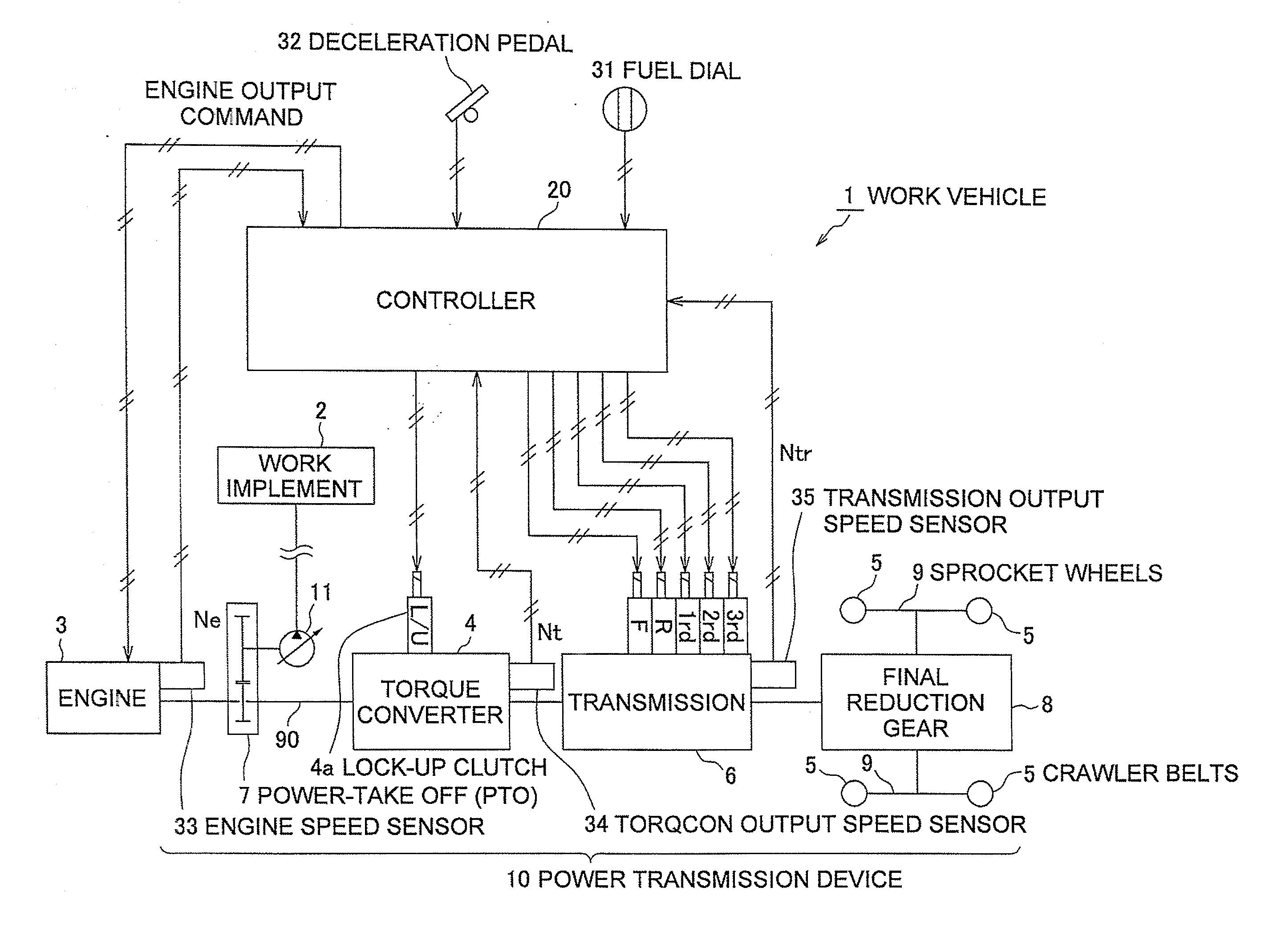
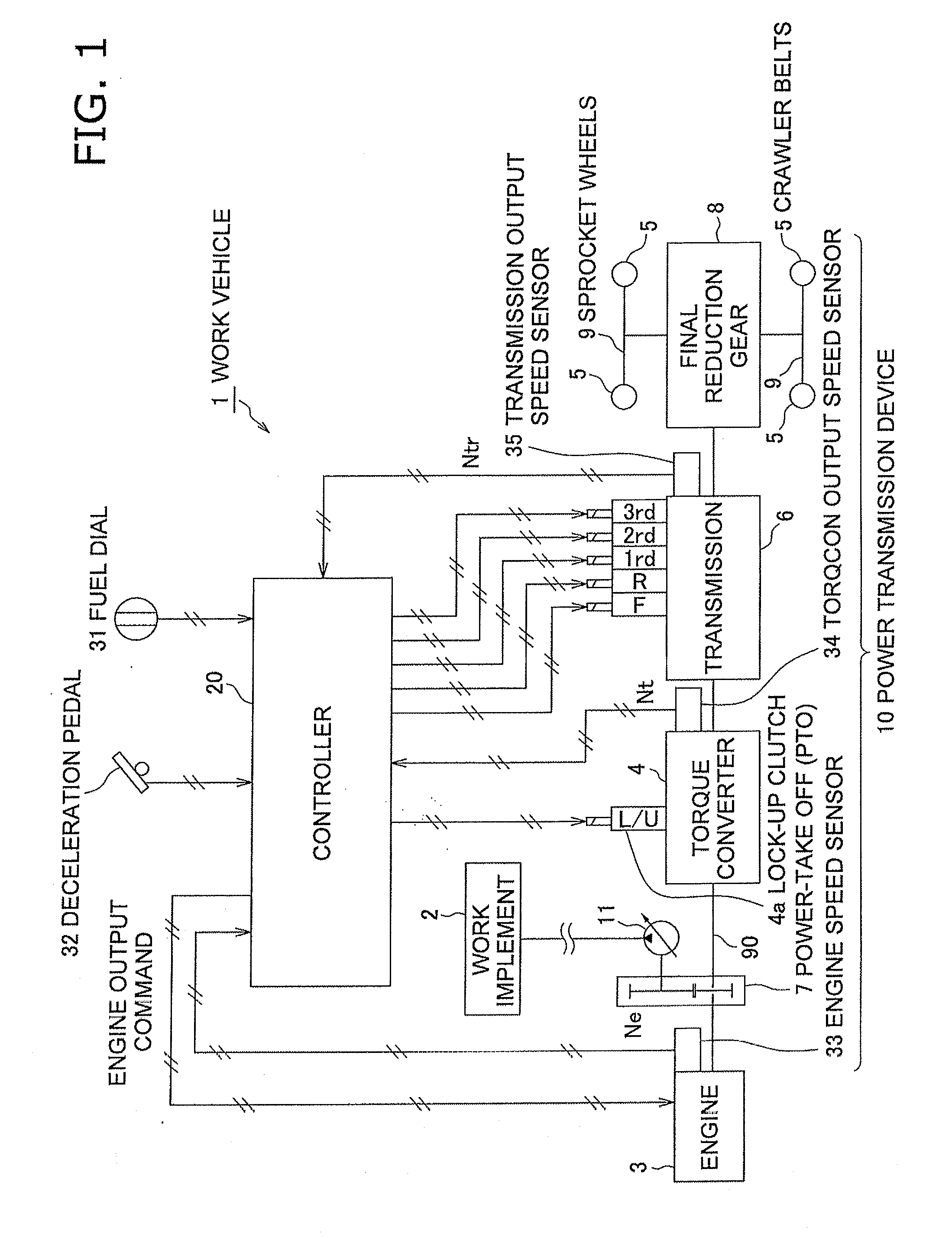
[0033]FIG. 1 is a block diagram for illustrating composition of an engine output control system of a work vehicle 1 according to the present embodiment. FIG. 1 illustrates some components of bulldozer's composition that are related to the present invention.

[0034]As illustrated in FIG. 1, the system of the present embodiment is an engine output control system assumed to be used for the work vehicle 1. The work vehicle 1 is composed of a work implement 2 including a blade, an engine 3 made up of a diesel engine, a travel device 5 composed of a pair of crawler belts, and a power transmission unit 10. The power transmission unit 10 includes a torque converter 4 with a lock-up clutch. The power transmission unit 10 is configured to transmit output of the engine 3 to the travel device 5 via the torque converter 4.

[0035]As illustrated in FIG. 1, a driving force transmission path 90 ranges f...


PUM


Abstract

An engine output control system is for a work vehicle composed of an engine, a travel device and a power transmission unit, the power transmission unit including a torque converter and transmitting an output of the engine to the travel device via the torque converter. The engine output control system includes a speed ratio computation portion and an engine output reduction control portion. The speed ratio computation portion is configured and arranged to compute a speed ratio of the torque converter. The engine output reduction control portion is configured and arranged to reduce an output torque of the engine without changing a target speed of the engine when the computed speed ratio is equal to or less than a speed ratio threshold set in advance. The speed ratio threshold is a speed ratio at which a torque ratio of the torque converter is greater than a torque ratio corresponding to a maximum efficiency.

Description

TECHNICAL FIELD[0001]The present invention relates to an engine output control system and an engine output control method that are applied to a work vehicle provided with a work implement in which engine output is transmitted to a travel device via a torque converter.BACKGROUND ART[0002]The bulldozer includes a work implement, an engine, a torque converter, a travel device, and a power transmission unit. The power transmission unit is configured to transmit engine output to the travel device via the torque converter. The travel device is composed of crawler belts (see Published Document 1).[0003]The bulldozer excavates the ground while pushing soil with the work implement (e.g., blade). When a large load acts on the vehicle in the excavation work of the work implement, the torque converter (hereinafter referred to as “torqcon” as needed) enters a completely / nearly stalled state. The term “completely stalled state” refers to a state that a speed ratio of the torqcon is zero. On the o...

Claims


Application Information

Patent Timeline
IPC IPC(8): G06F19/00
CPCF02D29/00B60W30/1882B60W30/1888B60W2510/0233E02F9/2066B60W2710/0677B60Y2200/25B60Y2200/41B60Y2400/426B60W2510/0275E02F9/2246
Inventor NAKAGAWA, TOMOHIROYAMAMOTO, SHIGERUSHIMADA, KENJIRO
Owner KOMATSU LTD
Why Eureka
Try Eureka