Apparatus for testing a conducted energy weapon

a technology of conducted energy and apparatus, applied in the field of conducted energy weapons, can solve the problems of poor or no electrical contact between one or both projectile darts and the skin of the intended victim, death in a limited number of cases where such weapons have been used, and negative effects

Inactive Publication Date: 2011-02-17
DATREND SYST
View PDF4 Cites 17 Cited by
  • Summary
  • Abstract
  • Description
  • Claims
  • Application Information

AI Technical Summary

Problems solved by technology

Although a CEW is intended to be non-lethal, deaths have occurred in a limited number of cases where such weapons have been used.
To what extent CEW use may have contributed to fatality in SDFR cases is controversial, and such controversy raises concern in the general public regarding safety of the weapons and the perceived risks of their use.
Such failure will arise in the case of a missed target, resulting in poor or no electrical contact from one or both projectile darts to the skin of the intended victim.
In cases where evidence of effective electrode contact can be verified, a negative outcome may then be attributable to reduced performance or malfunction of the weapon.
Such methods are limited in that they require significant technical expertise in setup and use of the apparatus.
More importantly, since CEW operation fundamentally relies on generation of spark discharges across one or more air gaps internal to the weapon, CEW signals as displayed by an oscilloscope may be corrupted by impulse artifacts, thus requiring significant skill on the part of the user of the apparatus to discern the true characteristics of the CEW signal from the superimposed impulse noise.
Compliance places significant economic and logistic burdens on such agencies, who must either internally develop the required technical resources and engineering competence to perform the recommended tests, or alternatively solicit costly testing services from external laboratories, for example NTS or MPB.
A limitation of CEW tests performed by CPRC, NTS, MPB and other laboratories is that specialist knowledge and experience is required to set up the necessary experiments and to correctly interpret signals which may be corrupted by impulse interference as previously described.
Apparatus and methods as taught by Kind and Feser are not suitable for use by peace officers or other personnel who may be associated with a law enforcement agency, and who may have limited understanding of high-voltage engineering and little or no training in the use of related laboratory apparatus and techniques.
A further limitation of CEW tests performed by CPRC, NTS, MPB and other laboratories is that the tests are entirely focussed on CEW conformance to the manufacturer's performance specifications.
To summarize the limitations described above, the prior art does not provide apparatus or method which will permit an individual who is not skilled in the art of high-voltage engineering and related laboratory technique, such as a peace officer, to measure and analyze the electrical output of a conducted energy weapon and in so doing derive an estimate of the risk of electrically stimulating a targeted subject to the point of serious injury or death.
Furthermore, the prior art does not provide apparatus or method which would permit a non-technical individual, such as a peace officer, to measure and analyze the electrical output of a conducted energy weapon and in so doing derive an estimate of the risk of failing to sufficiently stimulate a targeted subject to achieve incapacitation.
The prior art does not provide machine-based automation which would permit a non-technical individual, such as a peace officer, to make such technical and analytical determinations rapidly and easily, and in a way which is non-hazardous for the officer concerned.
Indicator means displays the risk of injury and warns the user when the risk exceeds a predetermined threshold.
Indicator means displays the risk of CEW failure to incapacitate and warns the user when the risk exceeds a predetermined threshold.

Method used


Image

  • Apparatus for testing a conducted energy weapon
  • Apparatus for testing a conducted energy weapon
  • Apparatus for testing a conducted energy weapon

Examples


Embodiment Construction

[0030]The embodiment illustrated herein is not intended to be exhaustive or to limit the invention to the precise form disclosed. It is chosen and described in order to explain the principles of the invention, and its application and practical use, and thereby enable others skilled in the art to utilize the invention.

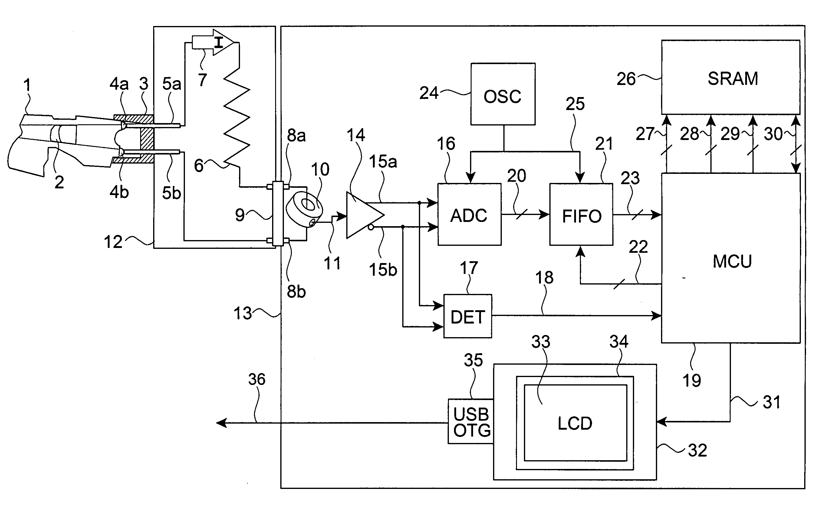
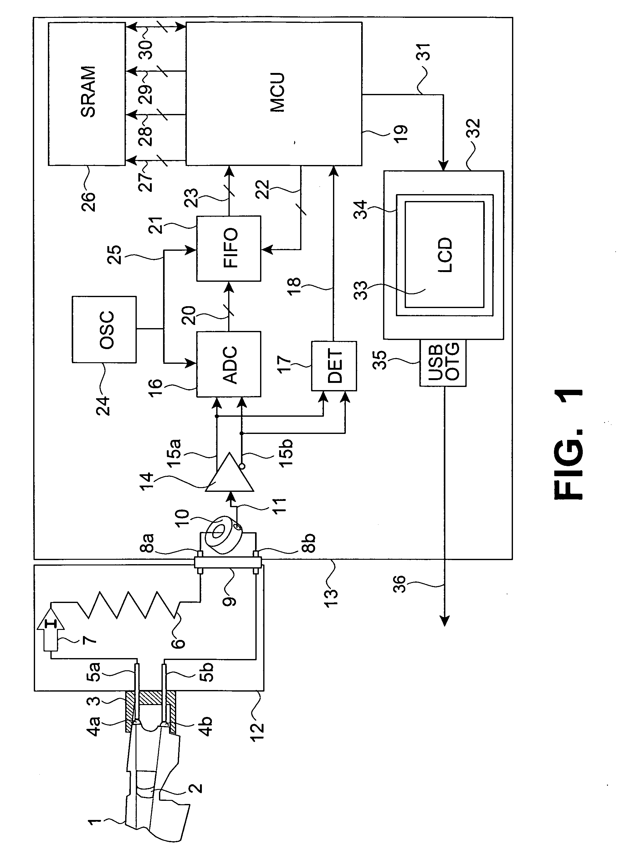
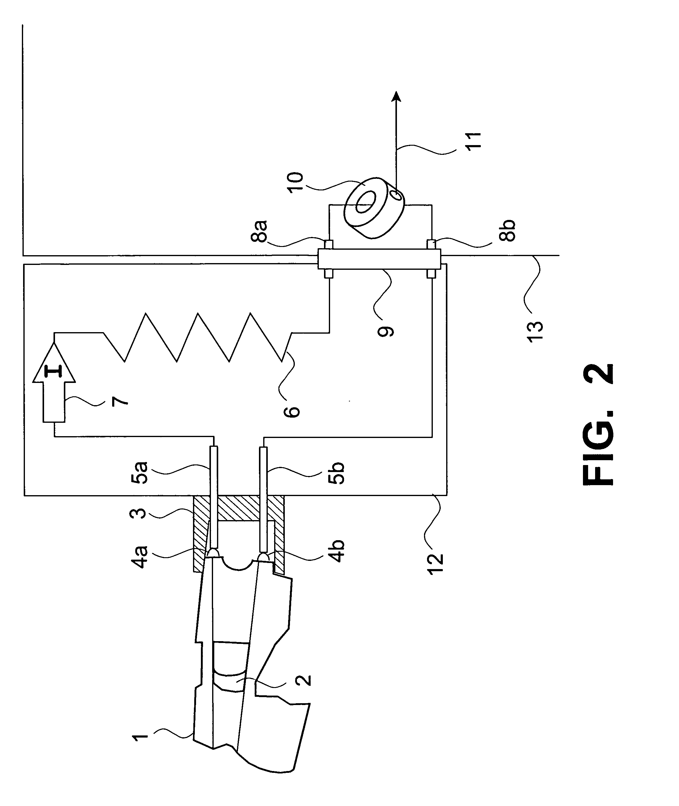
[0031]Apparatus for testing a conducted energy weapon 1 appears in the block diagram of FIG. 1, with specific details of weapon 1 being identified in FIG. 2. Referring to FIGS. 1 and 2, a conducted energy weapon 1 providing trigger 2 is inserted into receptacle 3, where a set of terminals 4a and 4b on weapon 1 connect to a resistive load 6 by means of spring-loaded contacts 5a and 5b. When trigger 2 of weapon 1 is actuated by a user of the apparatus, such as a peace officer, weapon 1 generates electrical current pulses 7 which are delivered from terminal 4a to one end of resistive load 6 as indicated in FIGS. 1 and 2. Via pin 8a of interface connector 9, electrical curr...


PUM


Abstract

Apparatus for testing a conducted energy weapon includes analyzer means to produce characteristic signals representative of characteristics of electrical current pulses delivered by the weapon into a resistive load when the weapon is discharged. Risk estimation means responsive to the characteristic signals produces a risk estimate representative of a risk of injury to a targeted subject due to electrical stimulation, or alternatively representative of a risk of failure to incapacitate the targeted subject. Indicator means responsive to the risk estimate indicates the risk of injury, or alternatively the risk of failure to incapacitate, and warns the user of the apparatus when the risk exceeds a predetermined threshold. Advantageously, automatic testing and risk analysis provided by the apparatus allows weapon tests to be easily and routinely conducted by persons having no knowledge of electrical principles, laboratory techniques, or risk analysis methodologies, such persons including peace officers or other individuals who may be associated with a law enforcement agency.

Description

FIELD OF THE INVENTION[0001]The present invention relates to conducted energy weapons, and more particularly, to means for testing the efficacy and safety of such weapons.BACKGROUND OF THE INVENTION[0002]A conducted energy weapon (CEW), variously known as an electronic disabling device, an electronic control device, or a “stun gun”, incapacitates a targeted subject by delivering a sequence of high voltage pulses to the skin by means of a pair of electrodes. Current which flows between the electrodes stimulates the target's neuromuscular system to produce involuntary muscle contractions, thereby disabling the subject. Depending on CEW design, the electrodes may contact the skin through direct application of the weapon to the subject's body, or by means of darts launched from the weapon which then penetrate the clothing of the target to reach the skin.[0003]In law enforcement, a CEW may be used by a peace officer for subduing a combative person in a scenario where application of signi...

Claims


Application Information

Patent Timeline
Patent Type & Authority Applications(United States)
IPC IPC(8): G01M19/00G01R27/08G06N5/00
CPCF41A31/00F41H13/0012G01R31/001F41H13/0025F41H13/0018
Inventor MILLER, MARK EDWARDEVANS, RONALD WILLIAM
Owner DATREND SYST
Why Eureka
Try Eureka