Coil tube heat exchanger for a tankless hot water system

a heat exchanger and tankless technology, applied in the field of coil tube heat exchangers, can solve the problems of unnecessarily warm top casting, increase fabrication and installation costs, and failure to harness and recover the maximum amount of energy, and achieve the effect of reducing the uneven distribution of hot flue gas

Active Publication Date: 2011-02-24
INTELLIHOT
View PDF27 Cites 49 Cited by
  • Summary
  • Abstract
  • Description
  • Claims
  • Application Information

AI Technical Summary

Problems solved by technology

However, the use of a ceramic disc inside the lumen takes up valuable heat exchanger footprint, increases fabrication and installation costs and fails to harness and recover the maximum amount of energy.
Poor heat recovery through the top casting further causes an unnecessarily warm top casting, waste to the environment and unnecessarily heats up surrounding components.

Method used


Image

  • Coil tube heat exchanger for a tankless hot water system
  • Coil tube heat exchanger for a tankless hot water system
  • Coil tube heat exchanger for a tankless hot water system

Examples


Embodiment Construction

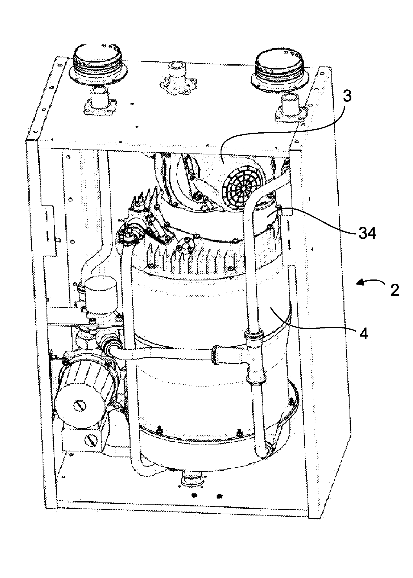
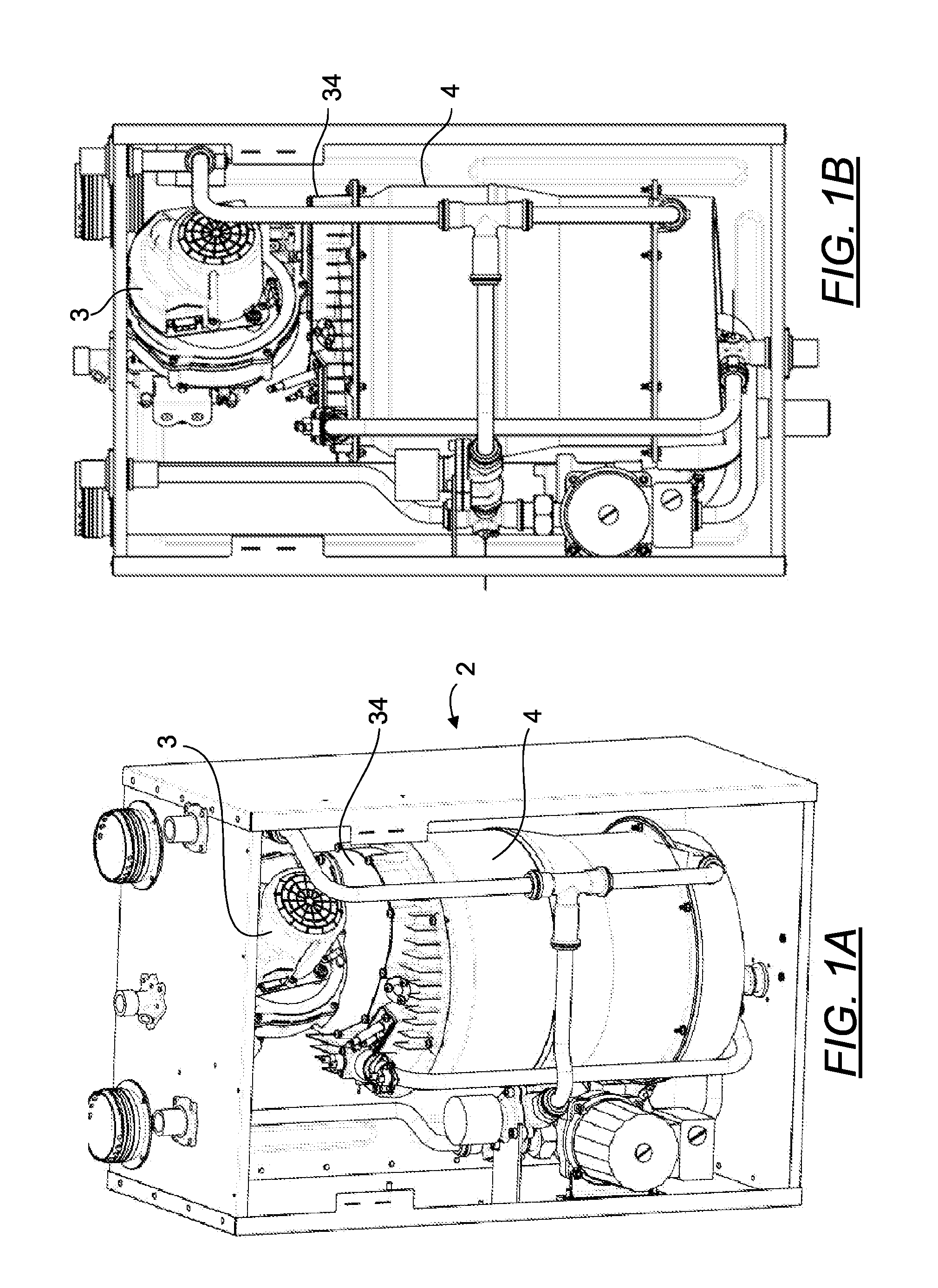
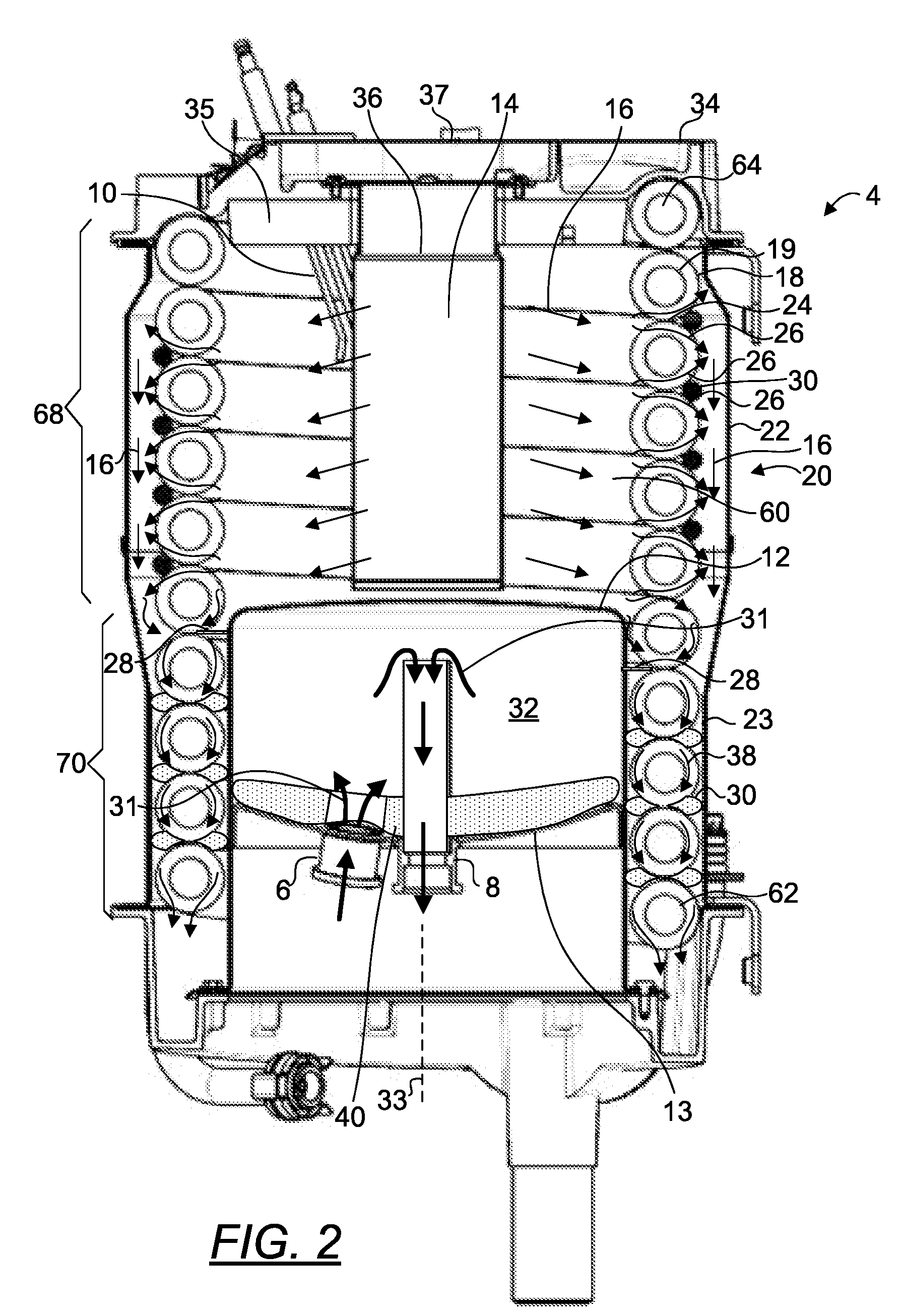
[0128]FIG. 1A is a top front perspective view of a hot water system including a heat exchanger 4. In use, the heat exchanger 4 receives a forced air / fuel mixture flow from a fan blower 3 connected to the heat exchanger 4. FIG. 1B is a front orthogonal view of the hot water system of FIG. 1A. FIG. 2 depicts a front orthogonal cross sectional view of the heat exchanger of FIG. 1B. The detailed description which follows describes the flow of water in the heat exchanger in the context of a tankless hot water system to aid in understanding of the inventive concept in one embodiment of its application. It is to be appreciated, however, that other fluids may be heated, such as for example, ethylene glycol in hydronic heating.

[0129]Referring to FIG. 2, the heat exchanger 4 comprises a top casting 34 and a finned helix coil 18 housed in a variable diameter cylindrical stainless steel housing 20. The housing 20 comprises a generally cylindrical wall, a lumen, an upper opening and a lower open...


PUM


Abstract

A novel water heat exchanger with a helix coil incorporated into a stainless steel elongated variable diameter cylindrical housing. A buffer tank is incorporated within the lumen of the helix coil. In one embodiment, the heat exchanger utilizes a radial direct-firing burner and a blower-driven hot flue gas to heat water for domestic and commercial use. In one embodiment, at least a rope seal is disposed between adjacent coil loops of a portion of the helix coil for enhancing heat transfer to the helix coil. In one embodiment, solar and electric heating systems are combined with the helix coil heat exchanger and disposed within the buffer tank to provide supplemental heating. In another embodiment, the heat exchanger further comprises a Stirling engine comprised of a free piston having hot and cold ends that is disposed within the cavity taken up the buffer tank, wherein the hot end receives heat from the burner and the cold end is cooled by the incoming cold water line to form an electric power generator.

Description

PRIORITY CLAIM AND RELATED APPLICATIONS[0001]This application claims the benefit of priority from provisional application U.S. Ser. No. 61 / 234,710 filed Aug. 18, 2009. Said application is incorporated by reference in its entirety.BACKGROUND OF THE INVENTION[0002]1. The Field of the Invention The present invention is directed generally to heat exchangers, and more particularly, to a coil tube heat exchanger for a tankless hot water system.[0003]2. Background Art[0004]In a tankless hot water system, a buffer tank is typically used as a limited energy storage device to meet sudden high hot water demand and to lessen the effects of temperature spike. In prior art tankless hot water systems having at least a fin-and-tube heat exchanger, a separate storage device is commonly used as the buffer tank and disposed externally from the fin-and-tube heat exchanger. The fin-and-tube heat exchanger comprises a generally cylindrical housing, a helix coil disposed concentrically inside the housing,...

Claims


Application Information

Patent Timeline
Patent Type & Authority Applications(United States)
IPC IPC(8): F24H1/18F24C11/00F24J2/30F28F1/36F24D18/00F24S10/30
CPCF24D2200/08F28F1/36F24D2200/26F24H1/186F24H1/208F24H1/34F24H1/43F24H9/0026F24H9/1836F24H2240/04F28D7/024F28F1/24F28F13/06Y02B10/20Y02B10/70F28F2215/04F28F2009/0292F28F2255/14F28F2265/12F24H1/165F28D1/0472F24D2200/14F24H1/44F24D2103/13F24D18/00F24D2103/17F24D2101/80
Inventor DEIVASIGAMANI, SRIDHARAKASAM, SIVAPRASAD
Owner INTELLIHOT
Why Eureka
Try Eureka