Check patentability & draft patents in minutes with Patsnap Eureka AI!

Adjustable Sprinkler Assembly

Inactive Publication Date: 2011-02-24
JEG
View PDF21 Cites 11 Cited by
  • Summary
  • Abstract
  • Description
  • Claims
  • Application Information

AI Technical Summary

Benefits of technology

[0007]The present invention is directed to an adjustable sprinkler assembly including a main housing having a cylindrical side wall provided with a first end portion that leads to a second end portion through an intermediate portion which collectively define a hollow interior portion. A riser member is shiftably mounted relative to the main housing to provide for adjustment of a sprinkler head attached thereto. The riser member includes an outer wall having a first end section that extends to a second end section through an intermediate section which collectively define an interior cavity. An adjuster member interconnects the riser member and the main housing and also provides for vertical displacement of the riser member to enable proper positioning of the sprinkler head.
[0010]In accordance with one aspect of the invention, the second end of the adjuster member is provided with an O-ring that seals against interior wall portions of the main housing. Preferably the second end of the adjuster member is provided with multiple O-rings to ensure that water, flowing to the sprinkler head, does not leak past the adjuster member and exit directly from the main housing. The O-rings also prevent dirt and other debris from entering into interior portions of the sprinkler assembly. In accordance with another aspect of the invention, the first end of the main housing is provided with a plurality of threads that are adapted to receive a locking collar provided on a fitting that is attached to a terminal end of a feeder pipe portion of an overall sprinkler system. Most preferably, the feeder pipe and main housing interconnect through a ball and socket arrangement that provides angular adjustment for the sprinkler head.

Problems solved by technology

This potential problem is typical in most golf course installations where sprinkler heads are often run over by work vehicles and golf carts.
Obviously, this represents a time consuming and expensive undertaking.
While these systems minimized excavation, adjustment generally requires various manipulations that can be cumbersome, require special tools and / or introduce dirt into the sprinkler head.

Method used


Image

  • Adjustable Sprinkler Assembly
  • Adjustable Sprinkler Assembly
  • Adjustable Sprinkler Assembly

Examples


Embodiment Construction

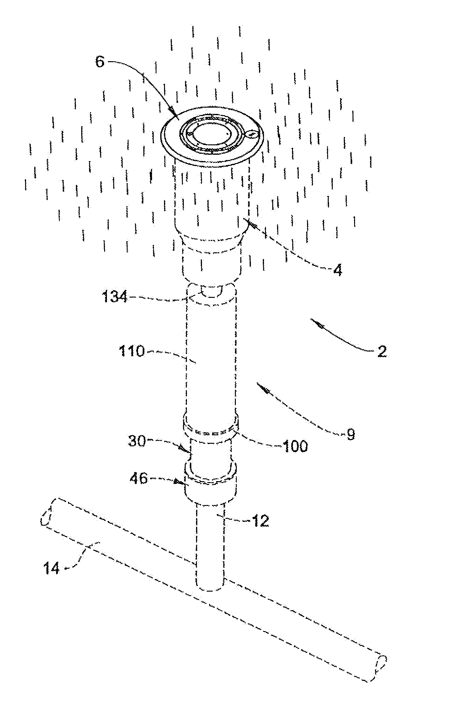
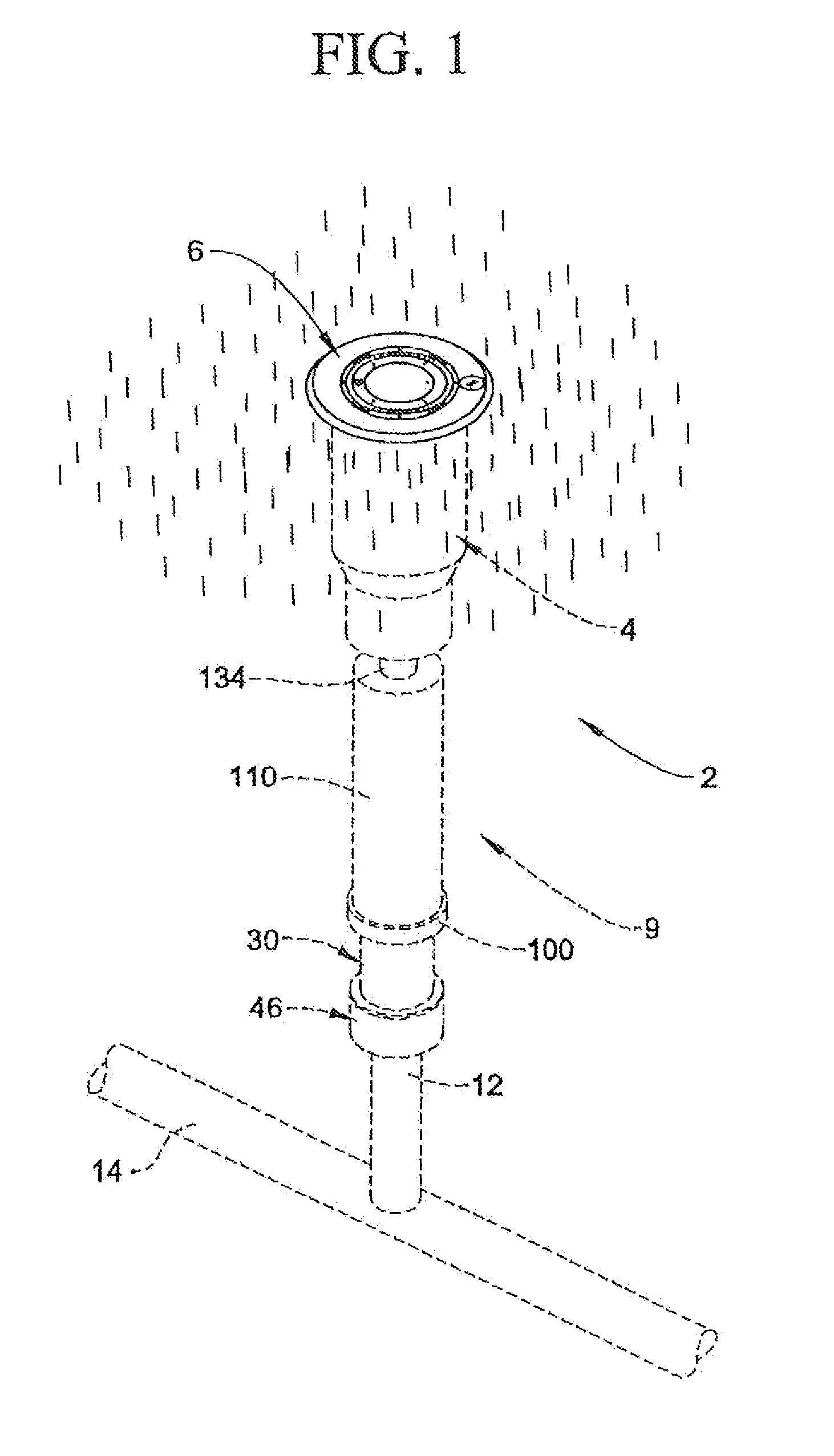
[0020]With initial reference to FIG. 1, an adjustable sprinkler assembly constructed in accordance with the present invention is generally indicated at 2. Sprinkler assembly 2 includes a sprinkler head 4 having a cap portion 6 and an adjuster portion 9. Adjuster portion 9 interconnects sprinkler head 4 with a feeder pipe 12 that extends from a subterranean irrigation system 14. As will be discussed more fully below, adjuster portion 9 enables installers to accurately position sprinkler head 4 relative to an upper surface of, for example, a lawn. That is, it is often desirable to ensure that cap portion 6 remains substantially flush with the upper surface of the lawn while, at the same time, enabling a sprinkler member (not shown), provided within sprinkler head 4, to pop-up and distribute water to surrounding grass, shrubbery, flowers and the like.

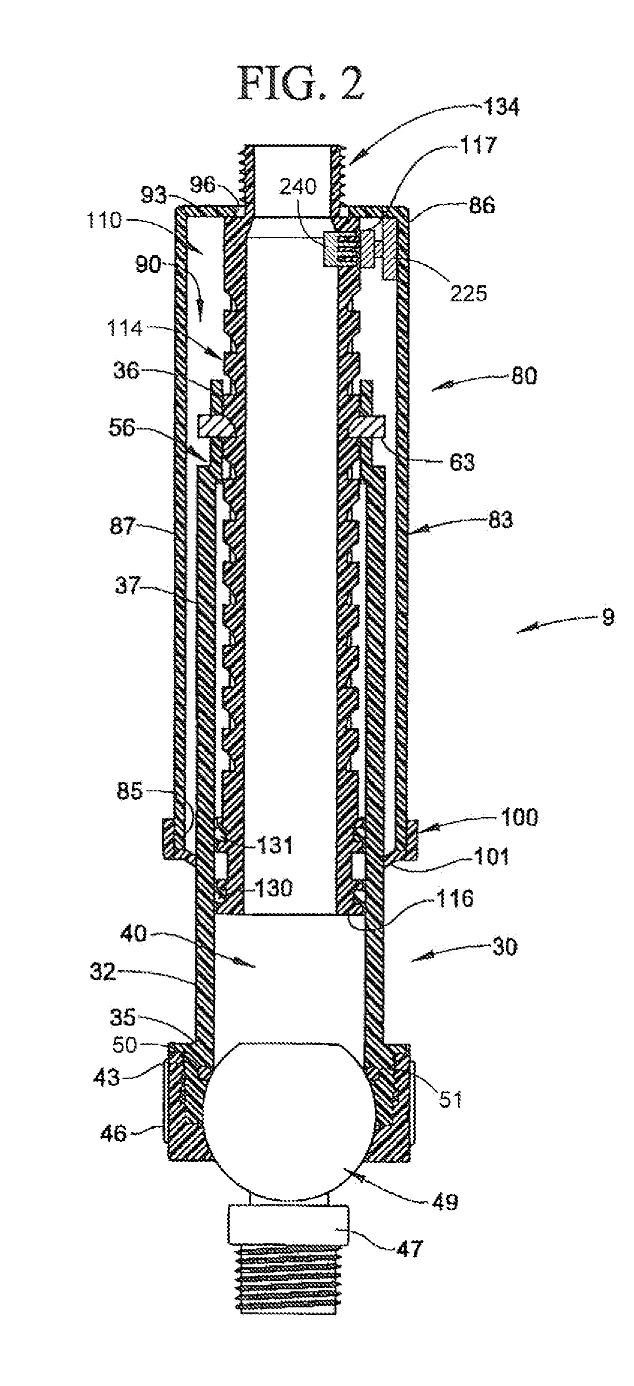
[0021]As best shown in FIGS. 2-4, adjuster portion 9 includes a main housing 30 having a generally cylindrical side wall 32 including a f...


PUM


Abstract

An adjustable sprinkler assembly incorporates a main housing including a cylindrical side wall having a first end portion that leads to a second end portion through an intermediate portion having a hollow interior. A riser member is shiftably mounted relative to the main housing to provide for adjustment of a sprinkler head attached thereto. An adjuster member, including an adjustment zone defined by a plurality of notches interconnected by a longitudinally extending groove, interconnects the riser member and the main housing. A stop member, mounted at the second end portion of the main housing, cooperates with the adjuster member to establish a desired positioning of a sprinkler head relative to the main housing.

Description

BACKGROUND OF THE INVENTION[0001]1. Field of the Invention[0002]The present invention pertains to the art of sprinkler systems and, more particularly, to an adjustable sprinkler assembly for a subterranean sprinkler network.[0003]2. Discussion of the Prior Art[0004]Subterranean irrigation or sprinkler networks having a number of vertically adjustable sprinkler assemblies connected to one or more main supply lines are widely known in the art. Typically, each sprinkler assembly includes a sprinkler head selectively positioned and operated for delivering water to irrigate grass, flowers, trees and the like over a particular area or zone. Because it is often desired to arrange the sprinkler head substantially flush with surrounding terrain and the depth to which the main supply line is buried can vary between different installations, sprinkler assemblies also include risers that interconnect the sprinkler head and the sprinkler networks. In order to accommodate the variation in depth, r...

Claims


Application Information

Patent Timeline
IPC IPC(8): B05B15/10
CPCB05B15/062B05B15/10B05B15/064B05B15/622B05B15/628B05B15/74
Inventor MCNULTY, EDWARD L.CORDOVA, GARY A.MEIER, JAMES
Owner JEG
Features
  • R&D
  • Intellectual Property
  • Life Sciences
  • Materials
  • Tech Scout
  • Unparalleled Data Quality
  • Higher Quality Content
  • 60% Fewer Hallucinations
Learn More