Illumination system and method for processing light

a technology of light and a filter system, applied in the direction of lighting devices, electrical devices, light sources, etc., can solve the problems of high cost and achieve the effect of large data transfer bandwidth and low cos

Active Publication Date: 2011-02-24
KONINKLIJKE PHILIPS ELECTRONICS NV
View PDF3 Cites 30 Cited by
  • Summary
  • Abstract
  • Description
  • Claims
  • Application Information

AI Technical Summary

Benefits of technology

[0004]The invention has as an objective providing an illumination system and method for processing light of the kind set forth which allows the use of low cost camera systems while still maintaining embedded codes invisible to the human eye and a sufficiently large bandwidth for data transfer. This object is achieved with the illumination system according to a first aspect of the invention as defined in claim 1. An illumination system comprising a plurality of light sources provided with an encoder arranged to enable light emitted from the light sources to comprise light source identification codes, a camera arranged to register images of illumination spots of the light emitted from the light sources, a signal processor arranged to derive the light source identification codes from registered images, CHARACTERIZED IN THAT the encoder is arranged to modulate the light emitted at a frequency above a predefined high level to comprise fast codes and at a frequency below a predefined low level to comprise slow codes. The invention provides an illumination system that advantageously allows the use of cheap slow camera systems for the light effect commissioning of the light sources and the determination of their footprints.
[0005]In an embodiment wherein the high level is 100 Hz and the low level is 10 Hz. Advantageously, this allows the light modulations to be practically invisible for the human eye. These values are based on the insight that the temporal sensitivity of the human eye is highly non-linear. At typical illumination levels of 100-500 lux the human eye's sensitivity as a function of the length of a light flash (i.e. the inverse of the code switching frequency) shows a very low sensitivity below 0.01 s (above 100 Hz). This allows for the fast code to be invisible. Moreover, the eye sensitivity decreases rapidly for pulse durations above 0.1 s (below 10 Hz) and leveling-off to a low sensitivity long pulse tail. Thus, as the long pulse tail does not reduce to zero the human visual system allows for the incorporation of slow codes in the light emitted at sufficiently small amplitudes to be visible for the camera while being invisible for the human eye. Low cost slow camera systems typically have a frame rate of 25-50 frames / s, excellently suitable for the detection of the slow codes in the foot print images.
[0006]According to an embodiment the illumination system further comprising a remote control device comprising a photo-sensor arranged to detect the fast codes allowing for rapid interaction of a user with the system.
[0009]In an embodiment of the invention the encoder 20 is arranged to implement the fast codes and slow codes using a spread spectrum technique. Advantageously, this allows the fast and slow codes to be detected without detrimental interference between the two.

Problems solved by technology

This results in a high cost solution.

Method used


Image

  • Illumination system and method for processing light
  • Illumination system and method for processing light
  • Illumination system and method for processing light

Examples


Embodiment Construction

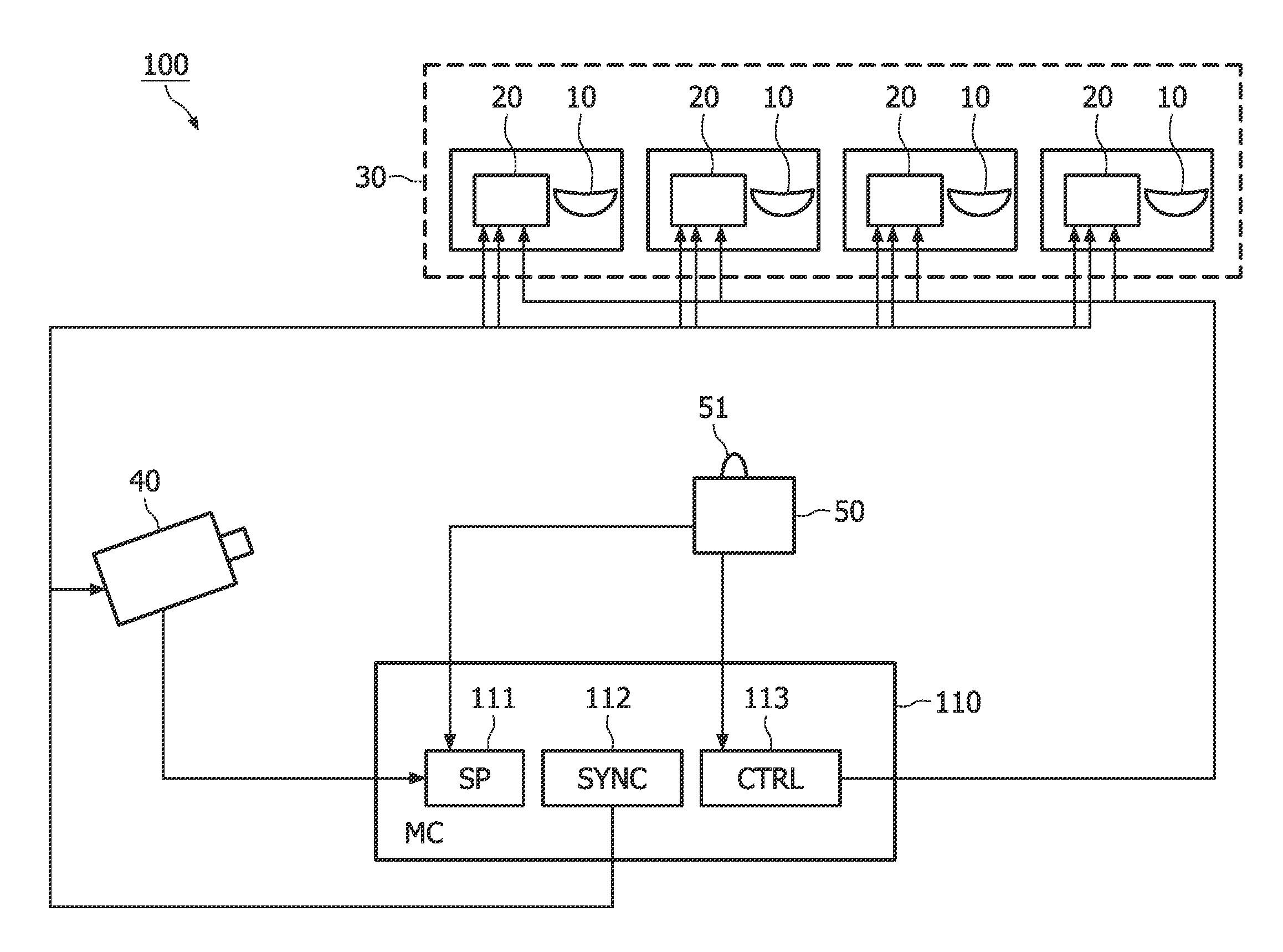
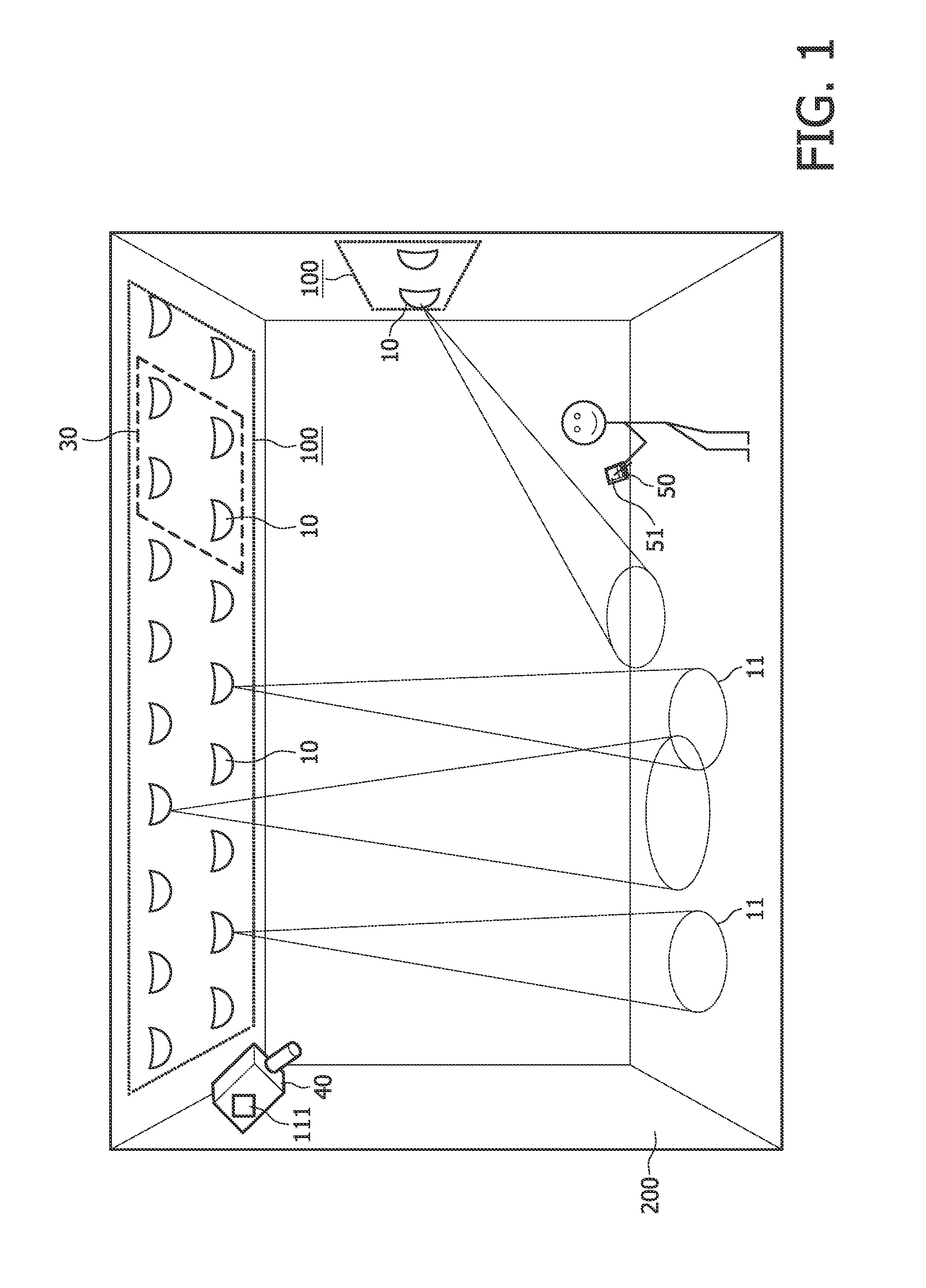
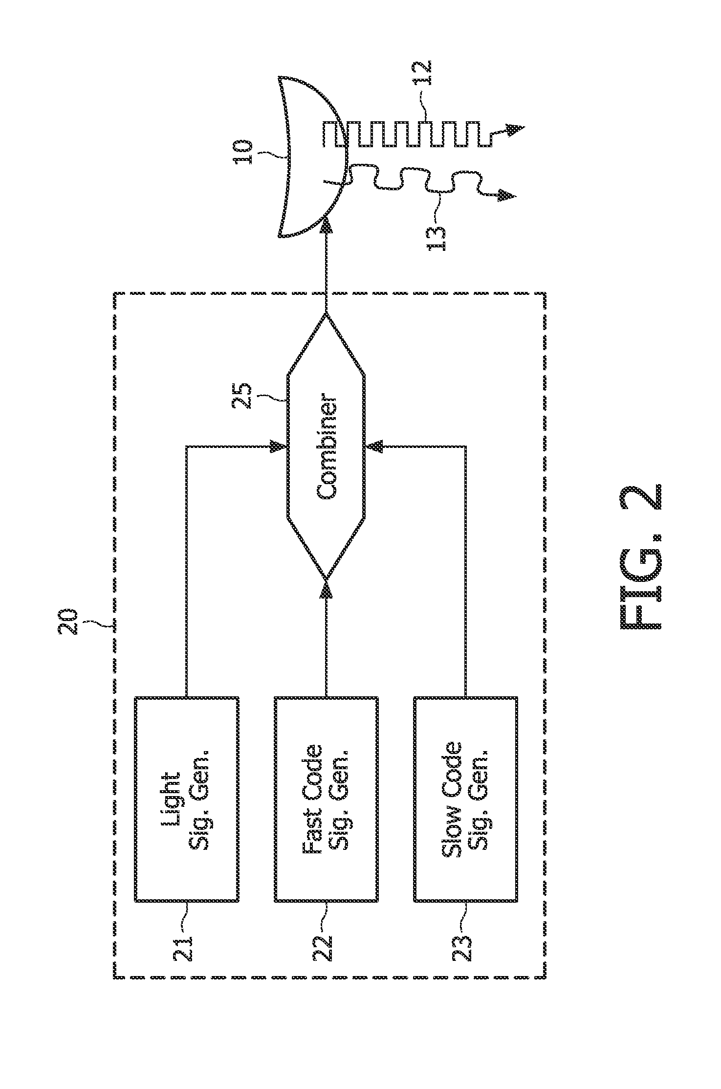
[0019]FIG. 1 shows structure 200—in this case a room—with an installed illumination system 100. The illumination system comprises a plurality of light sources 10, provided with an encoder (20—see FIG. 2) arranged to enable light emitted from the light sources to comprise light source identification codes. The light source may for instance be high / low pressure gas discharge bulbs, inorganic / organic LEDs, or laser diodes. Possibly several light sources 10 may be combined in a light module 30. The illumination system further comprises a camera 40 placed in the structure 200 enabling it to register images of illumination spots 11 of the light emitted from the light sources 10. A signal processor 111, f.i. incorporated in the camera 40 or in the master controller (110—see FIG. 3) of the illumination system 100, is arranged to derive the light source identification codes from registered images. Through the determination of the light source identification codes, it is possible to correlate...


PUM


Abstract

Proposed is an illumination system (100) comprising a plurality of light sources (10) provided with encoders (20) arranged to enable light emitted from the light sources to comprise light source identification codes. In order to enable light effect commissioning, i.e. correlating the light sources (10) with their illumination footprints (11), the system further comprises a camera (40) arranged to register images of illumination spots (11), and a signal processor (111) arranged to derive the light source identification codes from registered images. Arranging the encoders (20) to modulate the light emitted at a frequency above a predefined high level to comprise fast codes (12) and at a frequency below a predefined low level to comprise slow codes (13), beneficially allows for the use of simple low cost camera systems.

Description

FIELD OF THE INVENTION[0001]The invention relates to an illumination system and a method for processing light. Such systems and methods are in particular useful in the creation of illumination supported atmospheres and the light effect commissioning of the systems' light sources.BACKGROUND OF THE INVENTION[0002]Such systems and methods (as described f.i. in European Patent Application 07112664.3) for processing light in a structure, f.i. a room or a part thereof, a lobby, a vehicle, etc., typically include the arrangement of several light sources in the structure. The light sources emit light carrying individual codes, identifying the light source. Arranging a camera in a camera-position of the structure and registering images of spots of the light allows through the identification of the individual codes which light source contributes to an illumination pattern. The spots can be, for instance, illuminated areas on a floor, a wall, or ceiling. The image may even include the direct l...

Claims


Application Information

Patent Timeline
Patent Type & Authority Applications(United States)
IPC IPC(8): H05B37/02
CPCH05B37/034H05B37/0272H05B47/19H05B47/22
Inventor SCHENK, TIM CORNEEL WILHELMUSFERI, LORENZODAMINK, PAULUS HENRICUS ANTONIUSLINNARTZ, JOHAN PAUL MARIE GERARDYANG, HONGMING
Owner KONINKLIJKE PHILIPS ELECTRONICS NV
Why Eureka
Try Eureka