Fibre optic sensor

a technology of fiber optics and sensors, applied in the field of fibre optic sensors, can solve the problems of mechanical limits on the size of cells which can be generated, inherent limitations on the intensity of emitted signals, etc., and achieve the effects of reducing scattering reducing the intensity of incident light beams, and long path length

Inactive Publication Date: 2011-02-24
GLYSURE
View PDF7 Cites 4 Cited by
  • Summary
  • Abstract
  • Description
  • Claims
  • Application Information

AI Technical Summary

Benefits of technology

[0009]The cell of the present invention thus comprises a central portion which is longitudinally arranged, typically within the centre of the fibre. The intensity of incident light which is passed along the fibre is generally at its highest in the centre of the fibre. Locating the indicator in a central cell therefore maximises the intensity of incident light which reaches the indicator.
[0010]The cell is typically manufactured by laser ablating one or more holes extending across the fibre (e.g. radially across the fibre) to form the crossing portions, and subsequently laser ablating a hole extending longitudinally through the fibre, and intersecting with the crossing portions, to form the central portion. The initial formation of the crossing portions significantly facilitates the later formation

Problems solved by technology

This prior art design has a number of disadvantages, however.
However, there are mechanical limits on the size of cell which can be generated by the usual technique of laser ablation into the end of the

Method used


Image

  • Fibre optic sensor
  • Fibre optic sensor
  • Fibre optic sensor

Examples


Embodiment Construction

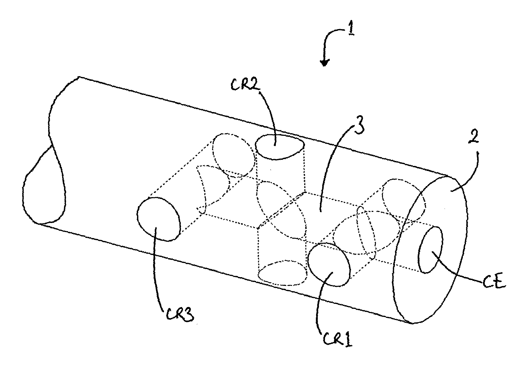
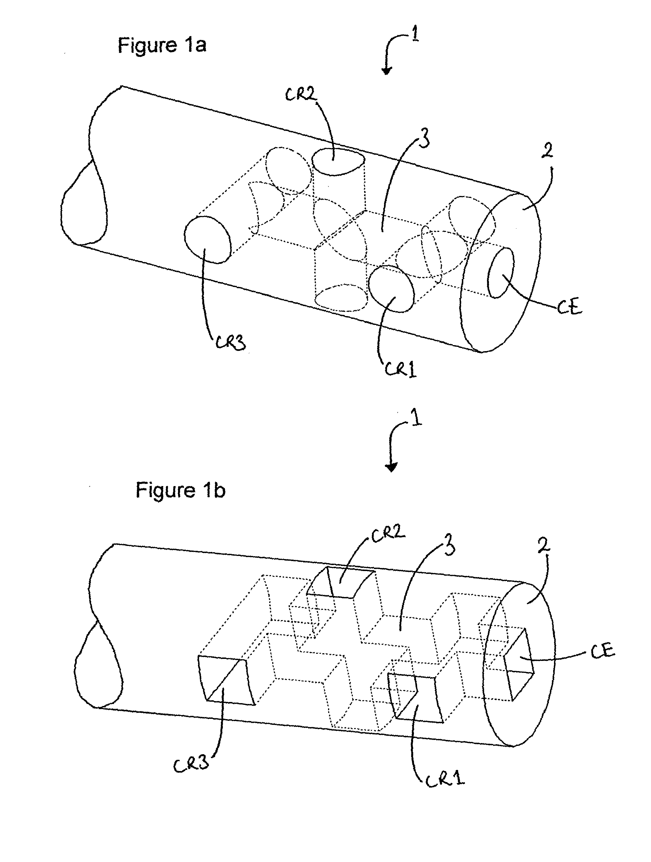
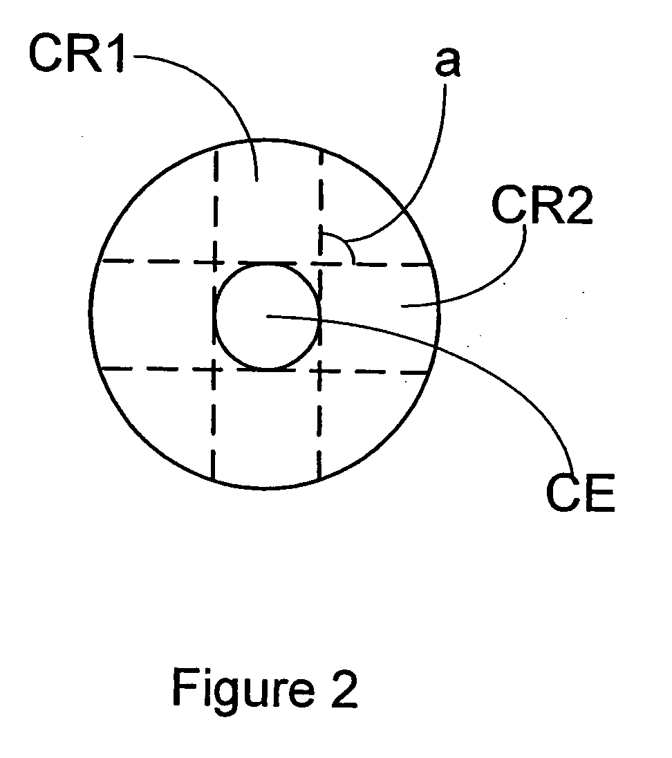
[0016]FIG. 1a schematically depicts the sensing region 1 of a fibre optic sensor of the invention and FIG. 2 provides an alternative view of the same sensor through a cross section of the sensing region. The sensing region is typically located at or near to the distal end, or tip, 2 of the fibre. During use, the sensing region is the part of the fibre which is in contact with the medium under study.

[0017]The sensing region comprises a cell (CE, CR1, CR2, CR3) which typically contains an indicator for the analyte. The indicator may be any material whose optical properties are altered in the presence of the analyte. Preferred indicators are those containing a fluorophore, although other indicators suitable for use in optical fibres are also envisaged, for example other luminescent indicators or absorbent indicators. Examples of suitable indicators are pH sensitive indicators, potassium indicators such as crown ethers, and indicators containing a boronic acid group and a fluorophore wh...


PUM


Abstract

A fibre optic sensor for detecting or measuring the concentration of an analyte in a medium, the sensor having a sensing region (1) for insertion into the medium during use, which sensing region comprises a cell containing an indicator for the analyte, wherein the cell comprises a central portion (CE) arranged longitudinally within the fibre and one or more crossing portions (CR1, CR2, CR3) which intersect the central portion.

Description

[0001]The present invention relates to a fibre optic sensor and a method for making a fibre optic sensor.BACKGROUND TO THE INVENTION[0002]Optical fibres have in recent years found use as chemical or biological sensors, in particular in the field of invasive or implantable sensor devices. Such optical fibre sensors typically involve an indicator, whose optical properties are altered in the presence of the analyte of interest. For example, fluorophores having a receptor capable of binding to the target analyte have been used as indicators in such sensors.[0003]Optical fibres can operate by passing incident light along the fibre and through one or more optical cells containing the indicator. In the case of an indicator containing a fluorophore, the incident light excites the fluorophore and causes emission of light of a different wavelength. The concentration of the analyte can be determined by measuring a property, typically the intensity, of the emitted fluorescent light (the signal)...

Claims


Application Information

Patent Timeline
IPC IPC(8): G02B6/00B29D11/00
CPCG01N21/0303G01N21/6428G01N21/7703G02B6/032G01N2021/7786G01N2021/7796G01N2021/7713
Inventor CRANE, BARRY COLIN
Owner GLYSURE
Why Eureka
Try Eureka