Fiber-optic extensometer

a fiber-optic extensometer and fiber-optic technology, applied in the field of extensometers, can solve the problems of inaccuracy of measurements, cracks or closes, and difficulty in precisely measuring the displacement in the system with bulky extensometers or strain gauge type sensors, and achieves the effects of reducing data acquisition rate, reducing transmitted power, and high sensitivity measuremen

Active Publication Date: 2011-02-24
POLYTECHNIC INSTITUTE OF NEW YORK UNIVERSITY
View PDF3 Cites 14 Cited by
  • Summary
  • Abstract
  • Description
  • Claims
  • Application Information

AI Technical Summary

Benefits of technology

[0018]In loops of multimode fibers, deformation of the loop leads to a reduction in transmitted power though the fibers in a linear fashion. However, transmitted power-displacement curves obtained in deformation of loops of single-mode fibers show several intermediate resonance peaks in otherwise linearly reducing curve. Therefore, it is possible to use the extensometers of the present invention in a dual measurement range. In the larger measurement range, the transmitted power-displacement curve can be approximated with a linear trend by ignoring intermediate resonance peaks. This can be practically achieved by having a lower data acquisition rate. In addition, the extensometers of the present invention can be used in a narrower measurement range, within two successive resonance peaks, to obtain high sensitivity measurements.

Problems solved by technology

When using extensometers to measure the displacement of a system, one problem that can occur that can result in inaccurate measurements is when the extensometer is applied across a crack to measure the crack opening or closing displacement.
The load applied by the extensometer can cause the crack to open or close.
In problems such as the opening of an existing crack under an applied load, it is difficult to precisely measure the displacement in the system with bulky extensometers or strain gauge type sensors.
Current strain gauges and fiber-optic sensors cannot provide direct measurement of displacement across such a crack because these devices are bonded to the structure.
Bonding these devices across the crack can significantly change the crack opening rate.

Method used


Image

  • Fiber-optic extensometer
  • Fiber-optic extensometer
  • Fiber-optic extensometer

Examples


Embodiment Construction

General Description

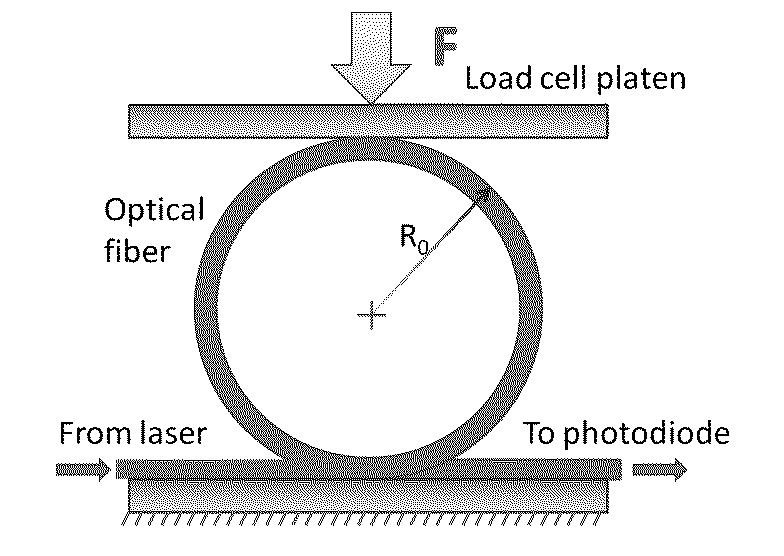
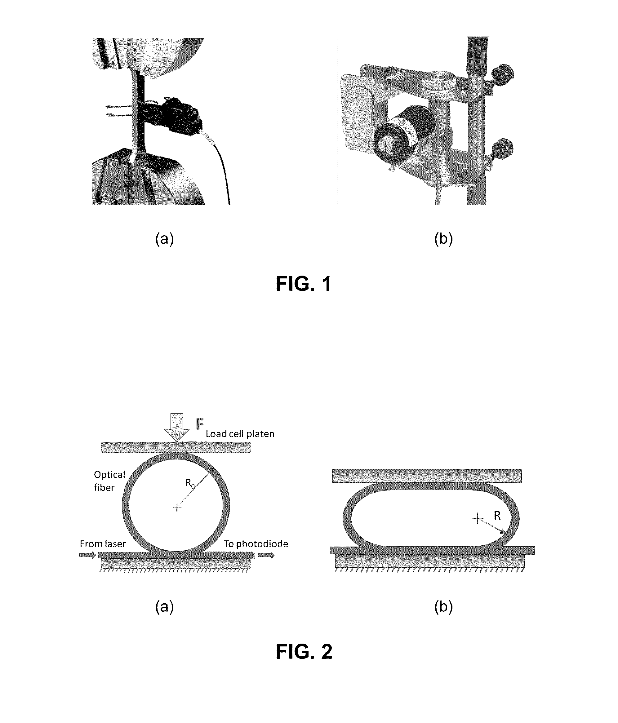
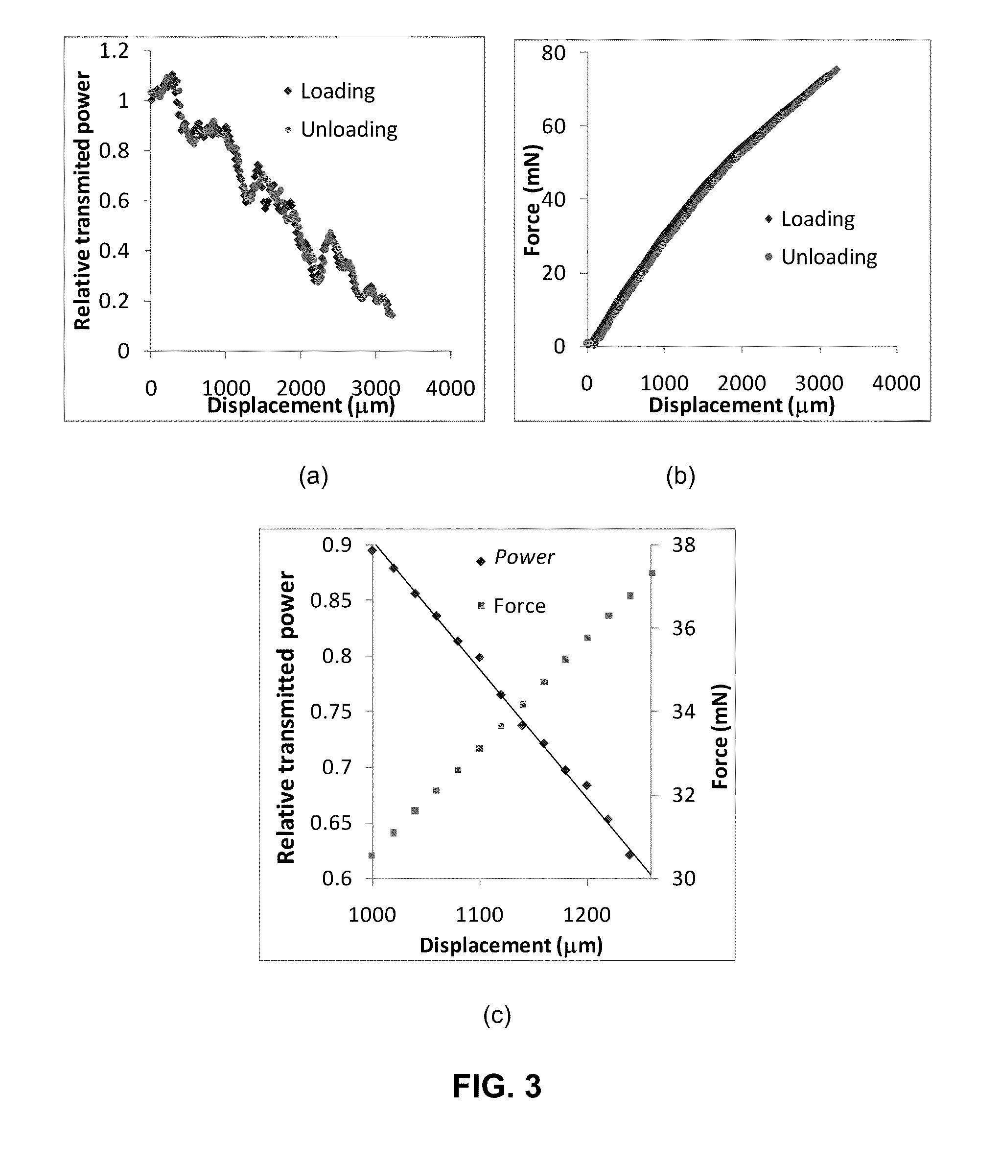
[0035]FIG. 2 illustrates an optical fiber loop sensor illustrative of the present invention and its working principle. As can be seen, the invention comprises an optical fiber loop that can be attached to a specimen, typically at two points, but the optical fiber loop also can be attached at multiple points, completely bonded to the specimen, or embedded inside of the specimen. FIG. 3 shows graphs of the loading and unloading of a representative optical fiber loop having a 6 mm radius. FIG. 3a shows the relative transmitted power (ratio of power transmitted through the deformed and undeformed loops) of the light through the loop. FIG. 3b shows the loop deformation with respect to the applied force. FIG. 3c shows correlation between the relative transmitted power, load, and displacement within one of the intermediate resonance peaks to show the possibility of a dual measurement range. Note that the slope of the relative transmitted power in FIG. 3c is two orders of...


PUM


Abstract

An extensometer having a loop of a single-mode optical fiber. At least two points of the loop are attached to desired locations on a specimen. Light is transmitted through the loop and the transmitted optical power is measured by a photodetector. The deformation of the specimen causes the size and shape of the loop to change, which changes the transmitted optical power. The change in optical power is related to extension or compression using calibration curves. The sensor works on the principle of transmitted power modulation through the curved section.

Description

STATEMENT OF RELATED APPLICATIONS[0001]This patent application is based on and claims the benefit of U.S. provisional patent application No. 61 / 235,378 having a filing date of 20 Aug. 2009, currently pending, which is incorporated herein in its entirety by this reference.BACKGROUND OF THE INVENTION[0002]1. Technical Field[0003]The invention is generally related to the field of extensometers and to the field of devices that measure the extension or strain in a specimen subjected to tension, compression, flexure, impact or other loading conditions. The invention also relates to extensometers that can be used across cracks and on surfaces with a high degree of roughness in a specimen.[0004]2. Related Art[0005]An extensometer measures the change of distance between two points on a specimen by attaching its two extension legs to the specimen and then activating the extensometer. FIG. 1 illustrates a known extensometer. Some problems in current extensometers include the generally large si...

Claims


Application Information

Patent Timeline
Patent Type & Authority Applications(United States)
IPC IPC(8): G02B6/00
CPCG01L1/243G01M5/0033G01B11/16Y02B10/30G01M5/0091
Inventor GUPTA, NIKHILNGUYEN, NGUYEN QUANG
Owner POLYTECHNIC INSTITUTE OF NEW YORK UNIVERSITY
Why Eureka
Try Eureka