Synchronized segmentally interchanging pulley transmission system

a transmission system and transmission line technology, applied in the field of transmission systems, can solve the problems of limiting the commercial viability of such systems, limiting the widespread utilization of such systems, and reducing reliability, so as to reduce the penalty of changing ratios, enhance acceleration, and expand the range

Active Publication Date: 2011-02-24
1783590 ONTARIO
View PDF24 Cites 18 Cited by
  • Summary
  • Abstract
  • Description
  • Claims
  • Application Information

AI Technical Summary

Benefits of technology

[0016]One feature of the present invention is the synchronization methodology. Some pulley segments are engineered to be, and are designated as, key pulley segments that enable the engagement of the endless drive member simultaneously with co-aligned pulley segments in multiple pulley segment sets of different radii during the transition from one pulley segment set to another. By virtue of utilizing key pulley segments to precisely engage the endless drive member with pulley segments in rapid sequence, the present invention has overcome the significant limitation related to high-speed ratio variation

Problems solved by technology

Certain mechanical problems persistently affect clutchless multi-ratio transmissions that limit their widespread utilization; specifically, the ability of such transmission systems to function at high speeds or under significa

Method used


Image

  • Synchronized segmentally interchanging pulley transmission system
  • Synchronized segmentally interchanging pulley transmission system
  • Synchronized segmentally interchanging pulley transmission system

Examples


Embodiment Construction

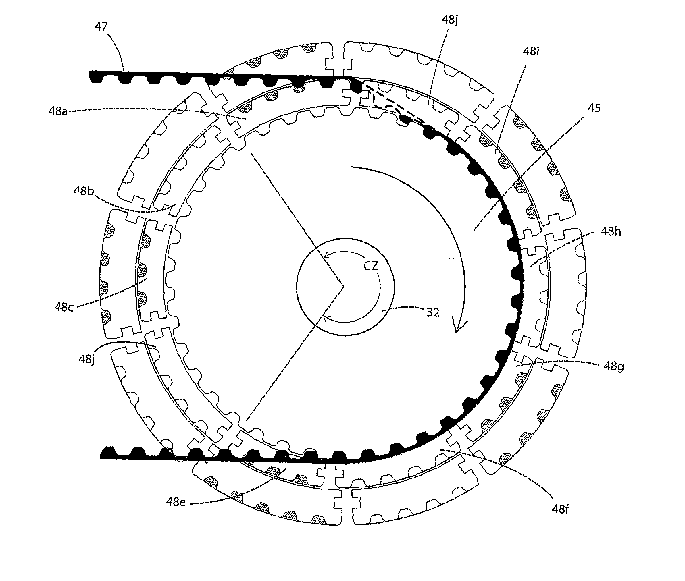
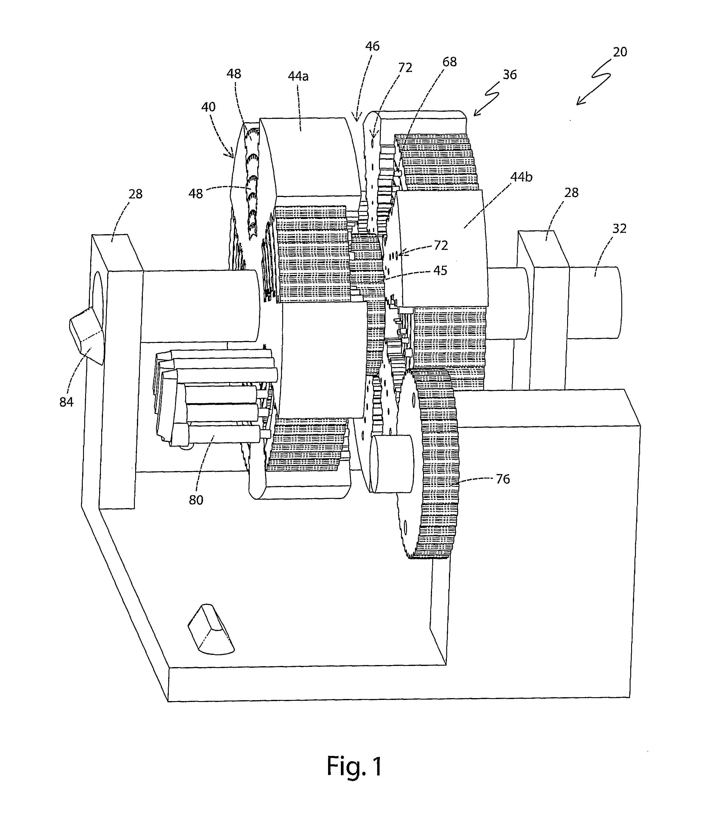
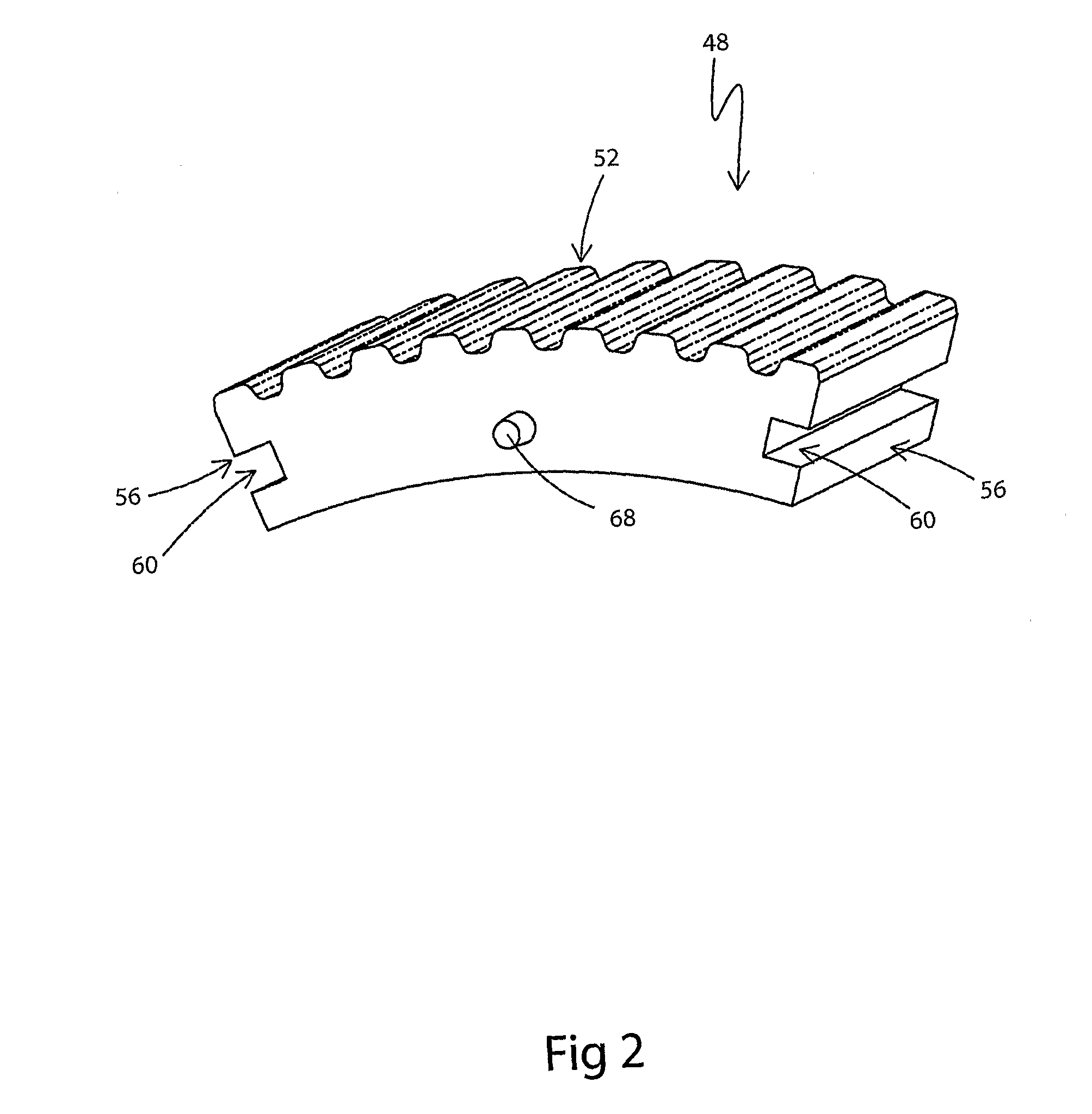
[0025]The present invention operates as part of a power transmission that changes ratio under load, and involves a plurality of pulleys, divided into segments, which segments move in channels or on rails along the rotational axis, into and out of the path of a toothed belt or chain. In this transmission system, as segments of a plurality of toothed, concentric and coaxial pulleys move axially, along channels or rails, into and out of the path of a toothed belt or chain, from either side of the belt or chain, pulley segment movement is coordinated by a synchronization and timing system, and the coordinated movement of pulley segments allows the belt or chain to change engagement between a plurality of concentric pulleys, without disrupting their rotation or the delivery of power through the belt or chain. This is accomplished by enabling the teeth of the belt to be continuously engaged by at least one toothed pulley, and at some points—when the belt is changing engagement between pul...


PUM


Abstract

A segmented pulley transmission is provided. A pulley assembly is rotationally mounted on an axle. The pulley assembly includes a core pulley having a first set of mating features on a peripheral surface thereof. A pulley segment set comprises a number of pulley segments slidably mounted in the pulley assembly and arranged in a ring concentric with the core pulley. The pulley segments are individually actuatable out of the pulley assembly into an engaging position and into the pulley assembly into a non-engaging position. The pulley segments have a second set of mating features on an peripheral surface matching the first set of mating features. An endless drive member has corresponding mating features on an inside surface for engaging the first and second sets of mating features of the core pulley and the pulley segments in an engaging position. Contact between the endless drive member and a core pulley defines a contact zone. An actuator actuates the pulley segments between the engaging and non-engaging positions when the pulley segments are outside of the contact zone. One of the key pulley segments in the pulley segment set is a key pulley segment that is positioned relative to the core pulley such that when the key pulley segment is actuated to the engaging position and rotated into the contact zone, the corresponding mating features of the endless drive member engage the first set of mating features of the core pulley and the second set of mating features of the key pulley segment without the introduction of significant slack or tension.

Description

CROSS-REFERENCE TO RELATED APPLICATIONS[0001]This application claims the benefit of U.S. Provisional Patent Application No. 60 / 572,075 filed May 19, 2004 and entitled SYNCHRONIZED SEGMENTALLY INTERCHANGING PULLEY TRANSMISSION SYSTEM.FIELD OF THE INVENTION[0002]The present invention relates to transmission systems, and more particularly to multi-ratio transmissions.BACKGROUND OF THE INVENTION[0003]There have been numerous attempts to develop a multi-ratio transmission capable of shifting under load over the past century. Potential applications for such a transmission system are numerous, including motor vehicles, human-powered vehicles, maritime craft, and even turbines for power generation.[0004]U.S. Pat. No. 1,428,999 to Tygard discloses a transmission system with axially-engaging, concentric nestable rims for varying a drive pulley diameter. U.S. Pat. No. 2,827,795 to Caballeros discloses a similar design utilizing a conical-shaped array of pulley segments. U.S. Pat. Nos. 5,443,42...

Claims


Application Information

Patent Timeline
IPC IPC(8): F16H9/12F16H9/24F16H55/52F16H55/54
CPCF16H9/24F16H55/52F16H9/04F16H55/54
Inventor WONG, ANTHONYBOTERRO, PAULDOYLE, MICHAEL
Owner 1783590 ONTARIO
Why Eureka
Try Eureka