Thermally isolated anchoring system

a technology of thermal isolation and anchoring system, which is applied in the direction of structural elements, buildings, building components, etc., can solve the problems of affecting the integrity of the system, affecting the stability of the system, so as to prevent air infiltration, prevent pin-point loading, and prevent disengagement.

Inactive Publication Date: 2011-03-03
MITEK HLDG INC
View PDF28 Cites 79 Cited by
  • Summary
  • Abstract
  • Description
  • Claims
  • Application Information

AI Technical Summary

Benefits of technology

[0037]The structure taught by this invention overcomes both the problems of pin-point loading and of insulation integrity described in the Background of the Invention hereinabove. The pin-point loading is overcome by full body support throughout the drywall, the air or air-vapor barrier, and the insulation. The interior seal, when the stud-type anchor is fully driven into place provides a seal over the insertion point into the air or air-vapor barrier. Similarly, the exterior seal, when the stud-type anchor is fully driven into place, provides a seal over the opening of an anchor-receiving channel and thereby preserves the insulation integrity. The polymeric components provide a thermal break between the inner and outer wythe and thereby maintain insulation R-values. The interior seal and the larger barrel of the anchor, when installed, completely fill the anchor receiving channel and stabilize the wall anchor. The wall anchor is clamped in place by the interior and exterior seals.
[0045]It is another feature of the present invention that the wall anchor has high-strength polymeric components that provide for a thermal break in the wall anchor.

Problems solved by technology

However, under certain conditions, the system did not sufficiently maintain the integrity of the insulation.
Besides earthquake protection, the failure of several high-rise buildings to withstand wind and other lateral forces resulted in the incorporation of a continuous wire reinforcement requirement in the Uniform Building Code provisions.
In general, the pintle-receiving sheetmetal version of the Seismiclip® interlock system served well, but in addition to the insulation integrity problem, installations were hampered by mortar buildup interfering with pintle leg insertion.
Upon experiencing lateral forces over time, this resulted in the loosening of the stud.
While the gapping was largely resolved by placing a self-sealing, dual-barrier polymeric membrane at the site of the legs and the mounting hardware, with increasing thickness in insulation, this patchwork became less desirable.
Contractors found that heavy wire anchors, with diameters approaching the mortar layer height specification, frequently result in misalignment.
However, the above-described technology did not fully address the adaption thereof to insulated inner wythes utilizing stabilized stud-type devices.
However, as there is no thermal break or barrier, a concomitant loss of the insulative integrity results.
Although steel offers many benefits, it does not provide the high insulation efficiency of timber framing and can cause the effective R-value of fiberglass batt insulation between the steel studs to fall 50 to 60%.
Removing the steel portions of the anchor at specific locations and replacing the steel with a high-strength polymeric material with a lower thermal conductivity than steel, causes a thermal break and significantly reduces the transfer of heat.

Method used


Image

  • Thermally isolated anchoring system
  • Thermally isolated anchoring system
  • Thermally isolated anchoring system

Examples


Embodiment Construction

[0060]Before entering into the detailed Description of the Preferred Embodiments, several terms which will be revisited later are defined. These terms are relevant to discussions of innovations introduced by the improvements of this disclosure that overcome the deficits of the prior art devices.

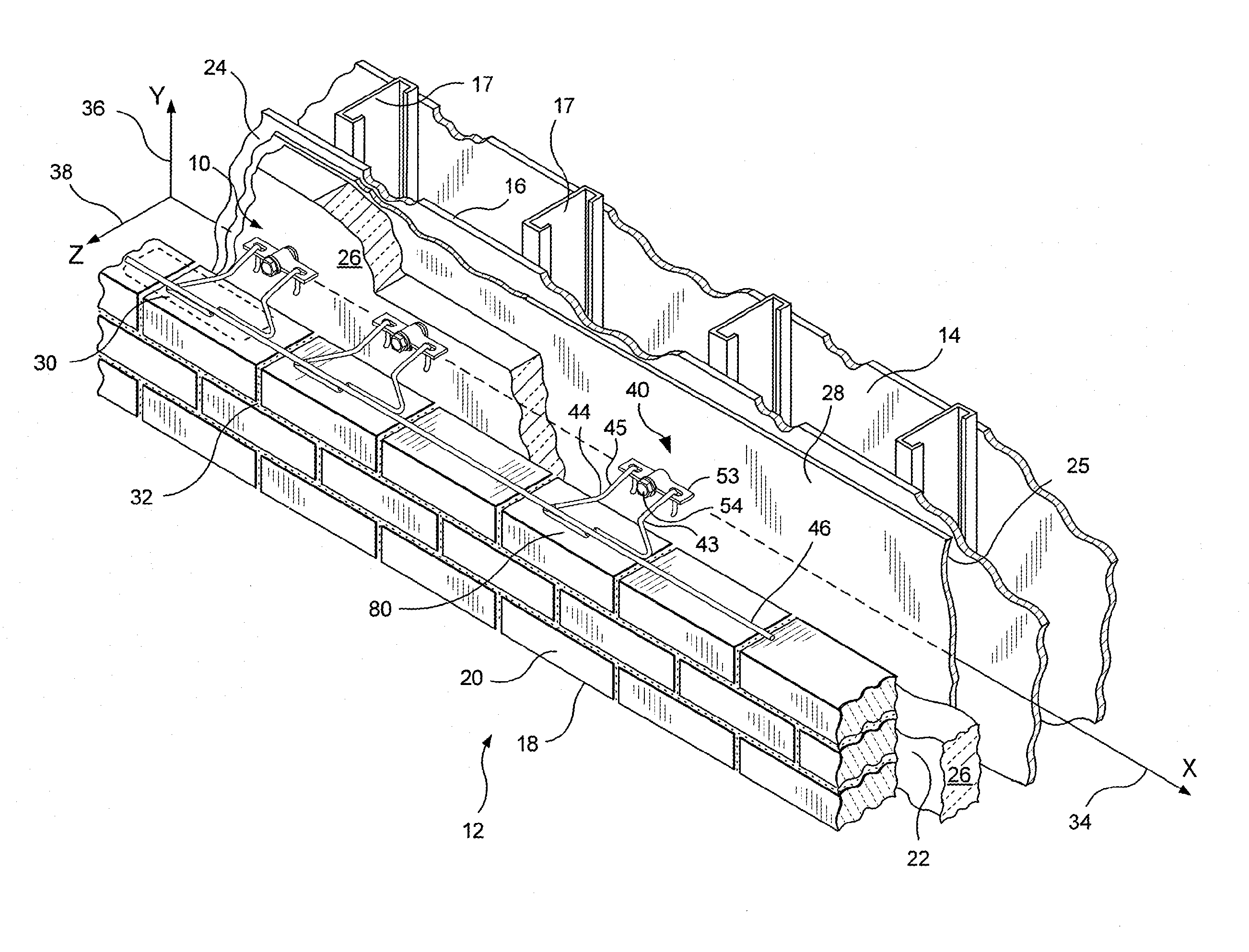
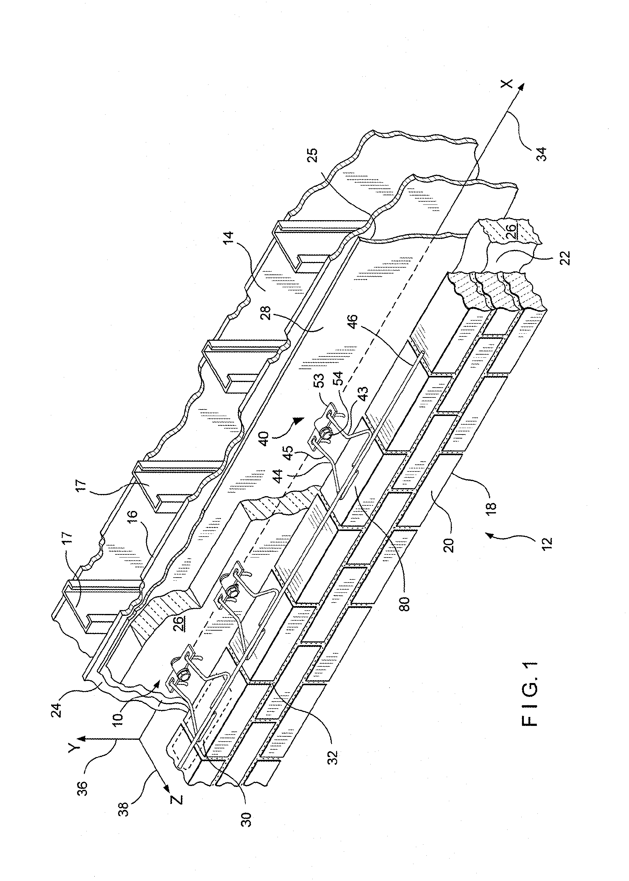
[0061]In the embodiments described hereinbelow, the inner wythe is provided with insulation. In both the dry wall construction and in the masonry block backup wall construction, shown herein, the insulation is applied to the outer surface thereof. Recently, building codes have required that after the anchoring system is installed and, prior to the inner wythe being closed up, that an inspection be made for insulation integrity to ensure that the insulation prevents infiltration of air and moisture. The term as used herein is defined in the same sense as the building code in that, “insulation integrity” means that, after the installation of the anchoring system, there is no change or interfere...


PUM


Abstract

An anchoring system for cavity walls is disclosed and includes a stud-type wall anchor and veneer tie. The stud is comprised of high-strength, nonconductive thermally-isolating components that maintain the insulation R-values. The stud has a driver head, dual-diameter barrel, and driven tip. A flange at the juncture of the two barrels houses an interior seal; a flange under the driver head, an exterior seal. The smaller diameter barrel is coextensive with the drywall installation; the length of the larger diameter barrel, with the rigid insulation. The interior seal seals the insertion point into the drywall installation; the exterior seal, the opening of the anchor-receiving channel. The interior seal and the larger barrel of the anchor fill the anchor-receiving channel and stabilize the wall anchor. The wall anchor is clamped in place by the seals. The anchor operates with various of veneer ties.

Description

BACKGROUND OF THE INVENTION[0001]1. Field of the Invention[0002]This invention relates to thermally isolated, dual sealing anchoring systems for insulated cavity walls. The anchoring system incorporates high-strength insulative polymeric components. The polymeric components minimize thermal transfer between the inner wythe and the anchoring system, by providing a thermal break.[0003]2. Description of the Prior Art[0004]In the past, anchoring systems have taken a variety of configurations. Where the applications included masonry backup walls, wall anchors were commonly incorporated into ladder- or truss-type reinforcements and provided wire-to-wire connections with box ties or pintle-receiving designs on the veneer side.[0005]In the late 1980's, surface-mounted wall anchors were developed by Hohmann & Barnard, Inc., patented under U.S. Pat. No. 4,598,518 ('518). The invention was commercialized under trademarks DW-10®, DW-10-X®, and DW-10-HS®. These widely accepted building specialty...

Claims


Application Information

Patent Timeline
Patent Type & Authority Applications(United States)
IPC IPC(8): E04B1/41
CPCE04B1/7616E04B1/4178
Inventor HOHMANN, JR., RONALD P.
Owner MITEK HLDG INC
Why Eureka
Try Eureka