
Hydraulic Bolt Tensioning Device and Method for Tightening Large Bolts by Means of a Hydraulic Bolt Tensioning Device

Active Publication Date: 2011-03-03
HOHMANN FRANK +1
View PDF11 Cites 11 Cited by
  • Summary
  • Abstract
  • Description
  • Claims
  • Application Information

AI Technical Summary

Benefits of technology

[0007]The invention has therefore the object to propose a hydraulic bolt tensioning device for tightening and releasing highly loaded screws and a method for controlling pressure loading of the hydraulic bolt tensioning device with which tearing off of the threaded bolt can be prevented.
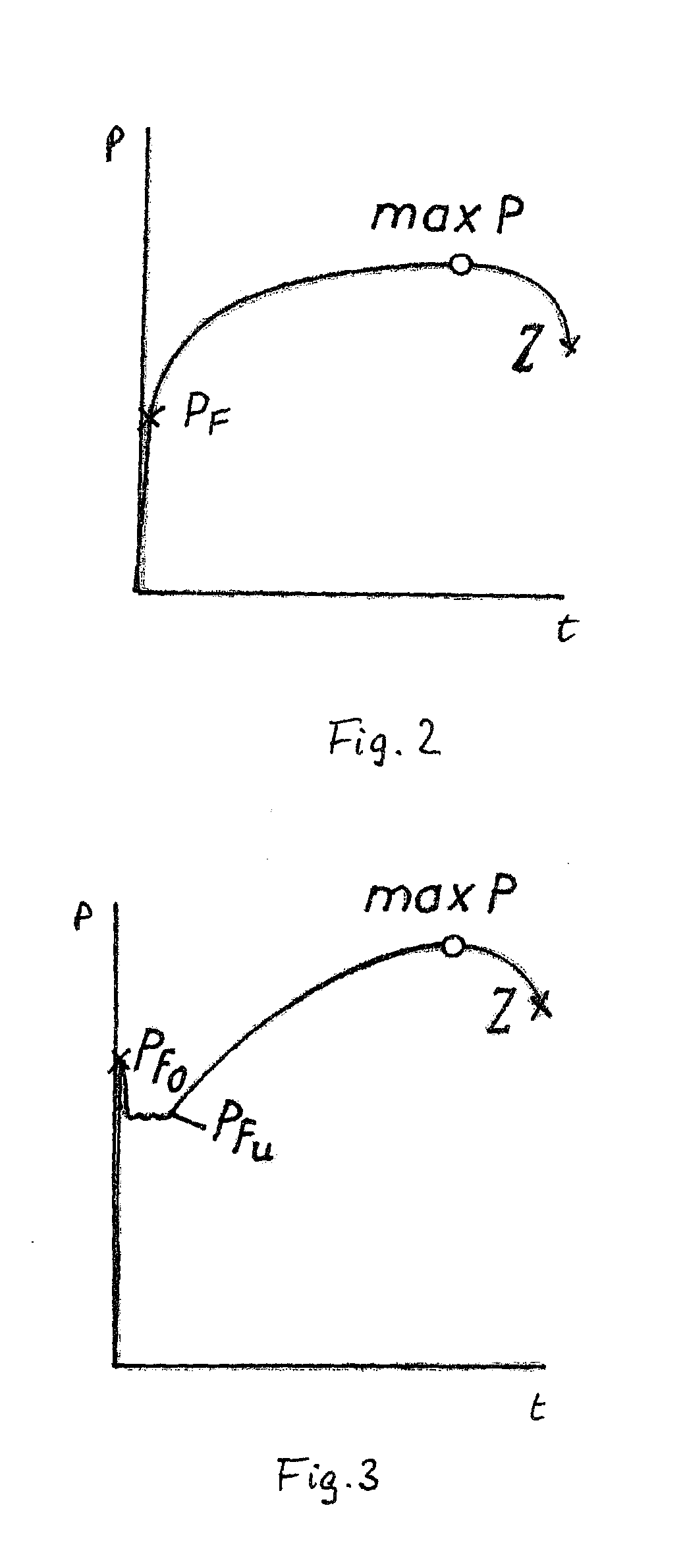
[0010]When the threaded bolt is already damaged, for example, at the thread or because of a material defect or by overloading above mechanically permissible parameters, an over-proportional lengthening of the threaded bolt will occur that causes rupture when no pressure relief of the bolt tensioning device is realized. Rupture of the threaded bolt can be prevented according to the invention with great reliability so that the bolt tensioning device also cannot be thrown off and damage to neighboring machine parts or injuries of operators can be prevented. It should be noted that the catching device described in DE 43 41 707 A1 will be effective only when the exchangeable bushing tears off but not when the threaded bolt will break.
[0014]Rupture of the threaded bolt can also be prevented when the differentiating device is designed such that the pressure relief is effected when the pressure gradient, before reaching the nominal pressure, is equal to zero, i.e., the pressure relief is realized when the maximum of the pressure / time curve is reached.

Problems solved by technology

When the threaded bolt is already damaged, for example, at the thread or because of a material defect or by overloading above mechanically permissible parameters, an over-proportional lengthening of the threaded bolt will occur that causes rupture when no pressure relief of the bolt tensioning device is realized.

Method used


Image

  • Hydraulic Bolt Tensioning Device and Method for Tightening Large Bolts by Means of a Hydraulic Bolt Tensioning Device
  • Hydraulic Bolt Tensioning Device and Method for Tightening Large Bolts by Means of a Hydraulic Bolt Tensioning Device
  • Hydraulic Bolt Tensioning Device and Method for Tightening Large Bolts by Means of a Hydraulic Bolt Tensioning Device

Examples


Embodiment Construction

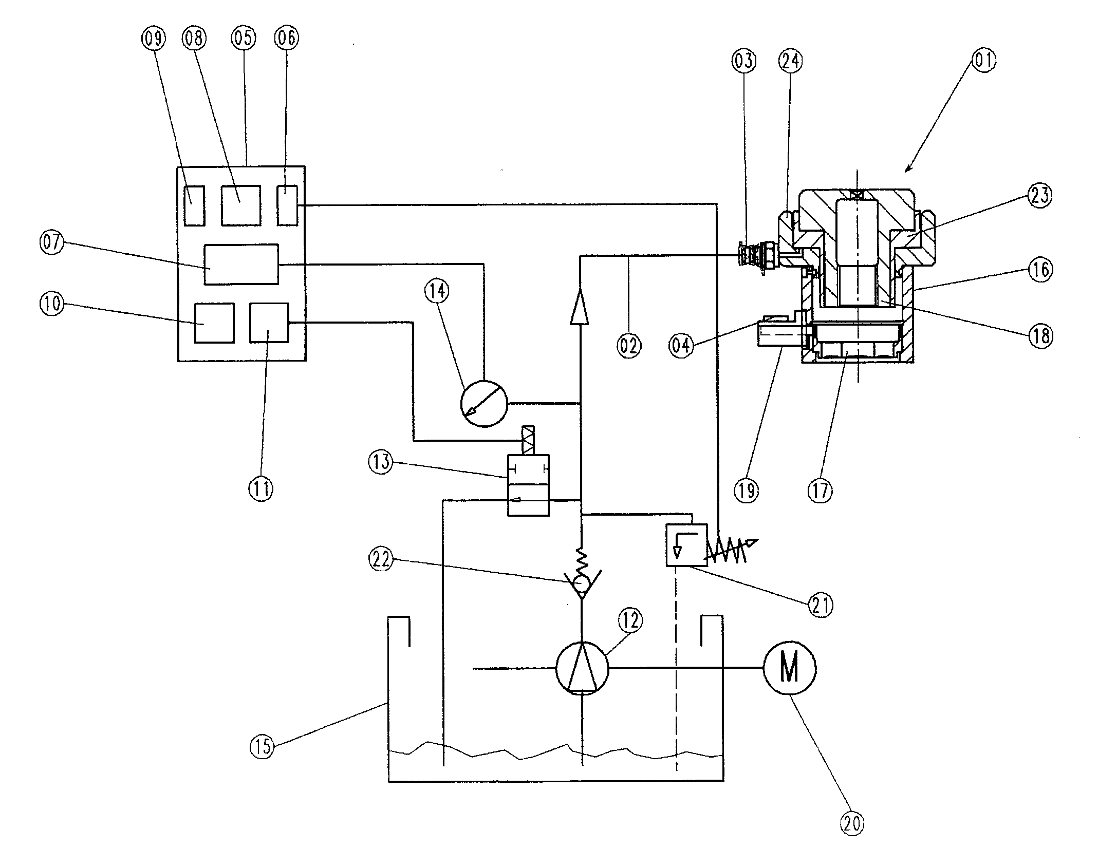
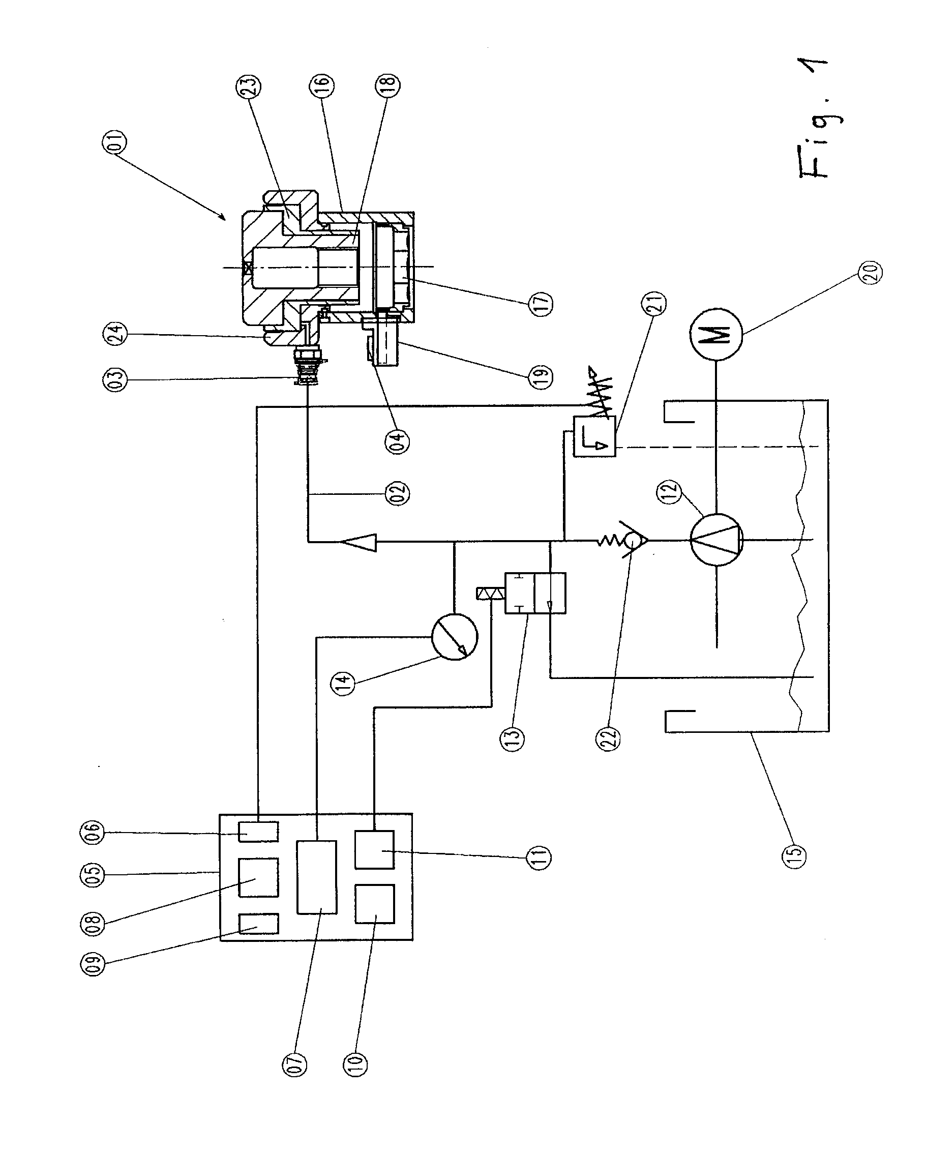
[0021]The hydraulic bolt tensioning device illustrated in the drawing and generally referred to by reference numeral 1 corresponds substantially to that of DE 43 41 707 A1 of the instant applicant.

[0022]A machine part, not illustrated, that e.g. may be a flange of a machine housing is to be clamped by means of a threaded bolt, also not illustrated, and a nut, not illustrated, that is screwed on.

[0023]In order to apply onto the threaded bolt a precisely controllable initial tension and in order to keep away torque from the threaded bolt that would constitute additional stress on the threaded bolt, the nut is screwed onto the threaded bolt initially by hand until the machine part is contacted. The length of the threaded bolt is dimensioned such that above the nut a free threaded end remains.

[0024]For tensioning the threaded bolt, the bolt tensioning device 1 is placed onto the nut that is screwed onto the threaded bolt wherein a rotary sleeve 16 provided with a hexagon socket 17 engag...


PUM


Abstract

A hydraulic bolt tensioning device has a cylinder supported on a machine part that is to be clamped by threaded bolt and nut. An exchangeable bushing has a first end screwed onto a free threaded end of the threaded bolt that projects past the nut. A tensioning piston is seal-tightly guided in the cylinder and supported on a second end of the exchangeable bushing. A pressure medium is supplied into an annular space between cylinder and piston. A control device is provided for setting a nominal pressure of the pressure medium corresponding to a nominal pretension of the threaded bolt. A yield limit detection device detects whether a yield limit of the threaded bolt is reached during tensioning. A controller acts on a pressure relief device for pressure relief of the bolt tensioning device when reaching, or shortly after reaching, the yield limit of the threaded bolt.

Description

BACKGROUND OF THE INVENTION[0001]The invention concerns a hydraulic bolt tensioning device for tightening and re-leasing highly loaded screws, comprising a cylinder that is supported on a machine part to be clamped by means of a threaded bolt and a nut; an exchangeable bushing that can be screwed onto a free threaded end of the threaded bolt; at least one pressure-loadable tensioning piston that is seal-tightly guided in the cylinder, is supported on an extension of the exchangeable bushing that is screwed onto the threaded end of the threaded bolt projecting past the nut, and forms with the cylinder an annular space; a pressure medium supply; an adjusting device for adjusting a nominal pressure corresponding to a nominal pretension; a device for pressure relief of the bolt tensioning device; and a pressure sensor.[0002]Such a hydraulic bolt tensioning device is disclosed in U.S. Pat. No. 7,469,592 (US 2008 / 0173140) of instant applicant.[0003]Bolt tensioning devices have the task of...

Claims


Application Information

Patent Timeline
IPC IPC(8): B25B21/00B25B23/145
CPCB23P19/067F16B31/043B25B29/02
Inventor HOHMANN, FRANKHOHMANN, JORG
Owner HOHMANN FRANK
Learn More