Parking gear for a motor vehicle

a technology for parking gear and motor vehicles, applied in the direction of braking systems, couplings, transportation and packaging, etc., can solve the problems of unacceptably altered engagement geometry of pawl and ratchet wheels, increased axial assembly space, and disadvantageous variations in friction coefficients

Inactive Publication Date: 2005-06-14
ZF SACHS AG
View PDF17 Cites 11 Cited by
  • Summary
  • Abstract
  • Description
  • Claims
  • Application Information

AI Technical Summary

Benefits of technology

[0011]The engagement wheel of the parking gear, which is designed as a ratchet wheel, is mounted in such a way that it can rotate relative to the drive shaft and, to allow rotational driving, is operatively connected with an element that cannot be rotated relative to the drive shaft. At least one elastically deformable element is mounted in the torque path between the engagement wheel and the rotationally fixed element, such that the elastically deformable element can absorb the residual rotational energy of the drive train, when the engagement wheel is locked by the locking element. This design makes it possible, on the one hand, to produce a reliable locking effect of the drive shaft and thus a secure parking position of the vehicle, and, on the other hand, to smoothly dissipate any residual rotational energy still present in the drive train at the instant of engagement of the pawl, so that damage to drive train components and other parts of the vehicle is reliably prevented. The parking gear of the invention can be favorably operated in dry operation.
[0017]An especially useful configuration for saving assembly space is obtained when the engagement wheel and the flange are mounted in essentially the same axial position, i.e., they are arranged radially with respect to each other on the drive shaft.
[0018]It is especially advantageous to design the webs of the flange and the engagement wheel to be narrower than the corresponding gaps between the webs. If the webs of one element are positioned in the middle of the gaps of the other, chambers with a U-shaped cross section are obtained, into which elastic elements that likewise have an essentially U-shaped cross section fit. The emergency brake is thus suited for locking the drive train in both directions of rotation.
[0022]The use of an elastomer as the material for the elastic element has been found to be very advantageous.
[0023]When several elastic elements are used, they can be joined by connecting elements, e.g., webs or film hinges. This greatly simplifies their installation in the emergency brake and saves installation time.

Problems solved by technology

A disadvantage here is that, when the ratchet wheel is suddenly locked, the finely tuned engagement geometry of the pawl and ratchet wheel is unacceptably altered.
However, the spring effect requires a suitable special material, and the requisite frictional forces require a large contact force or a large frictional diameter.
Furthermore, dry operation results in disadvantageous variations in the coefficients of friction.
Furthermore, in the case of radial limitation of the space available for the component parts, several frictional surfaces, i.e., several disks, are necessary, which in turn leads to an increased axial assembly space.
On the other hand, limitation of the assembly space in the axial direction results in relatively large frictional diameters.
Here again, we run into the above-described problems with respect to limitation of assembly space and dry operation.

Method used


Image

  • Parking gear for a motor vehicle
  • Parking gear for a motor vehicle
  • Parking gear for a motor vehicle

Examples


Embodiment Construction

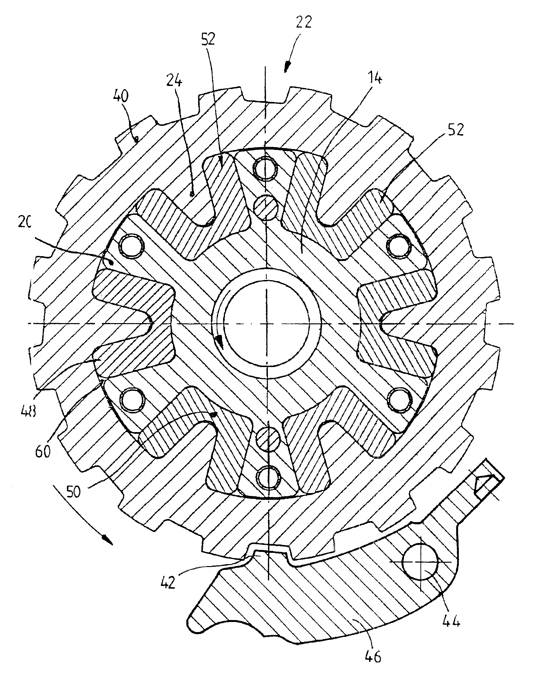
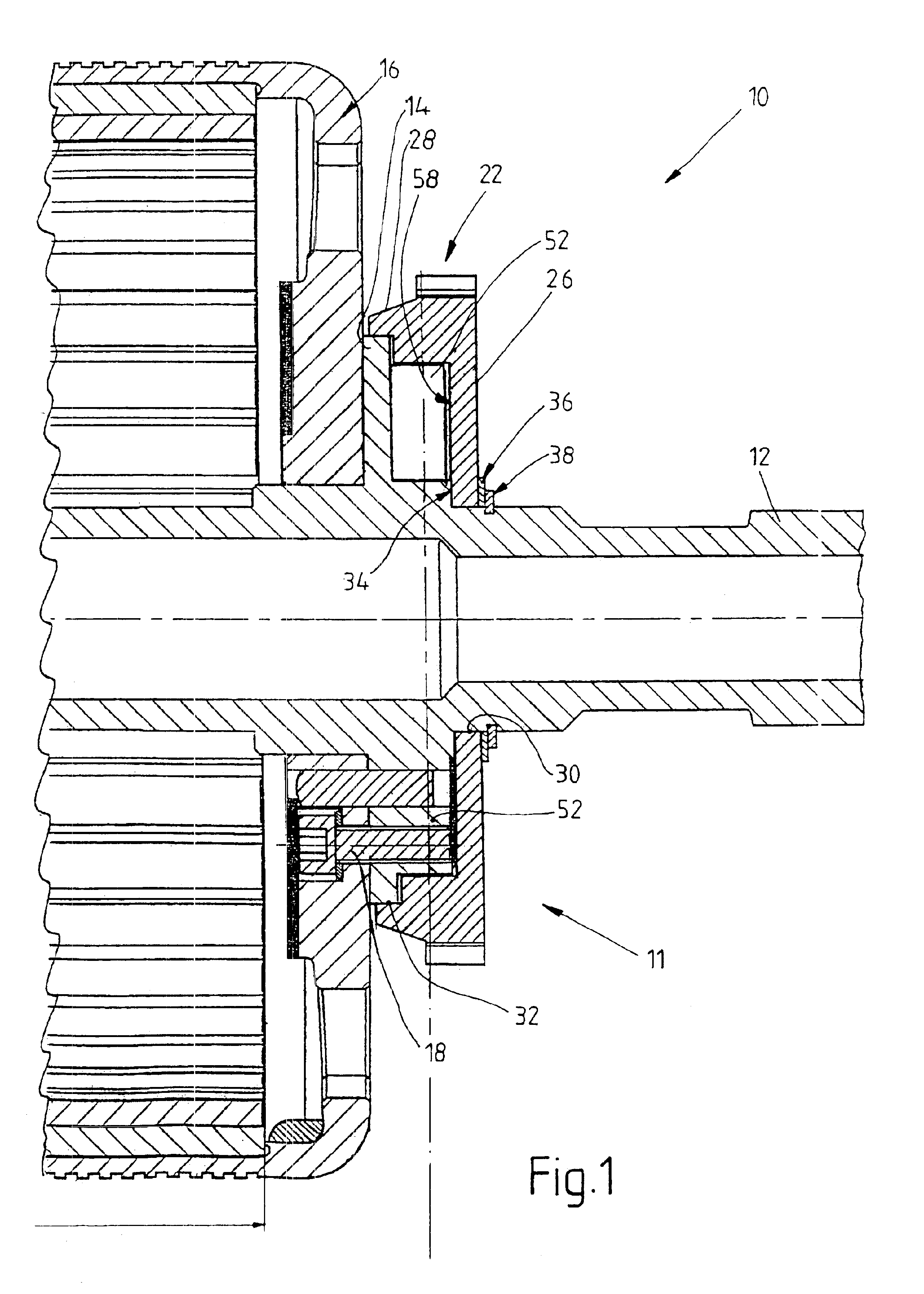
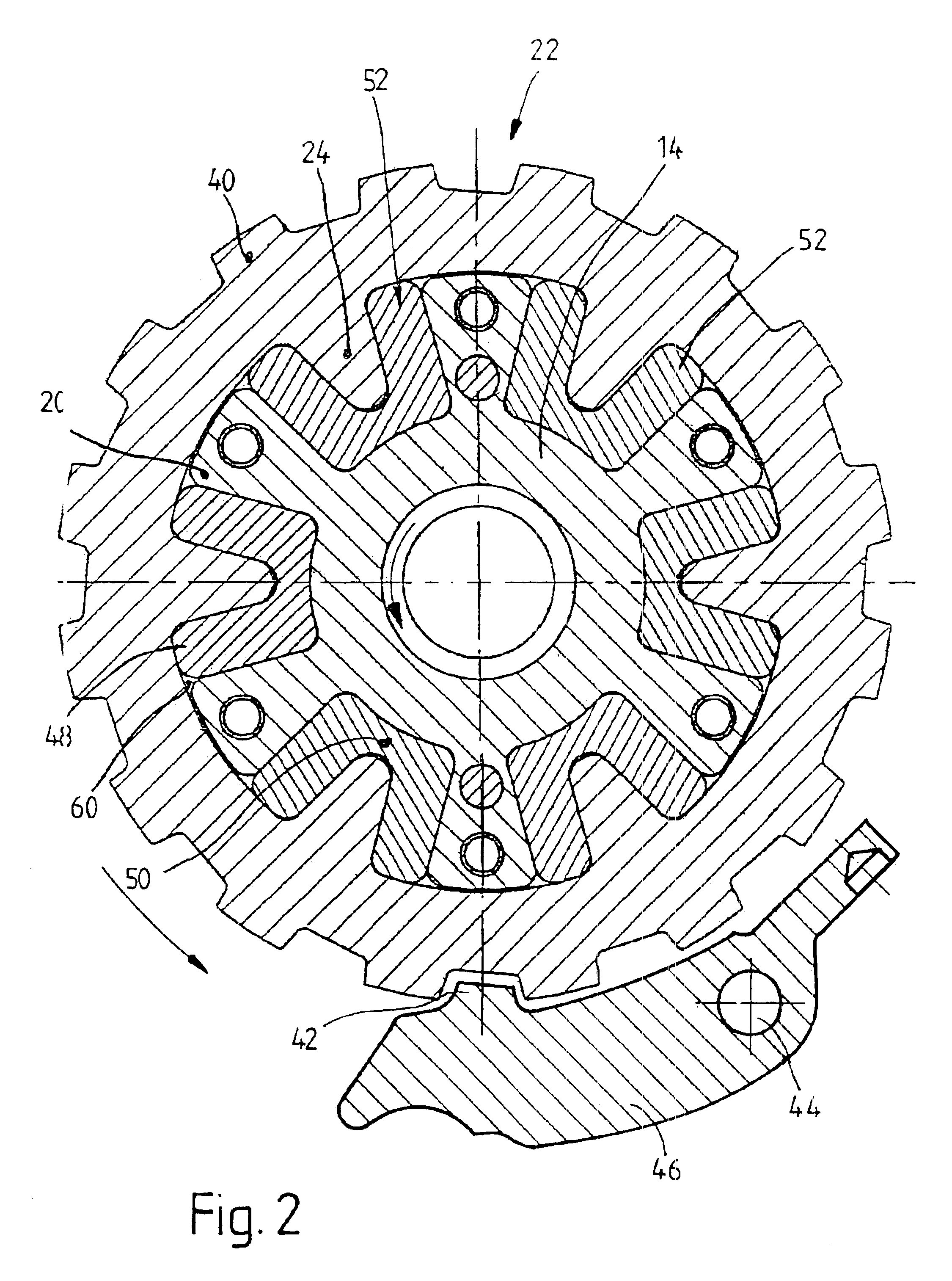
[0028]FIG. 1 shows a cutaway section of a drive train 10 of a motor vehicle with a parking gear 11. The drive gears (not shown) are operatively connected with a drive shaft, in this case, the transmission input shaft 12. The rotor 16 of an electric external-rotor motor (not further shown) is fastened to the drive shaft 12 by means of a rotationally fixed flange 14 with a bolt 18. The use of the invention is not limited to a combination with a specific type of electric motor. As FIG. 2 shows, a number of webs 20 that run radially outward are formed on the flange 14. An engagement wheel in the form of a ratchet wheel 22 is installed on the side of the flange 14 that is axially opposite the rotor 16. It is installed concentrically with the flange 14 in essentially the same axial position. The ratchet wheel 22 has the same number of webs 24, but in this case the webs run radially inward. The flange webs 20 and ratchet wheel webs 24 thus form form-fitting profiles, such that the webs of ...


PUM


Abstract

An engagement wheel is mounted so that it can rotate relative to the drive shaft of a drive train in a motor vehicle. To allow rotational driving, the engagement wheel is operatively connected with an element that cannot be rotated relative to the drive shaft by at least one elastically deformable element mounted in the torque path between the engagement wheel and the rotationally fixed element. The elastically deformable element can absorb residual rotational energy of the drive train, when the engagement wheel is locked by a locking element, which may be in the form of a pawl.

Description

BACKGROUND OF THE INVENTION[0001]1. Field of the Invention[0002]The invention concerns a parking gear for a motor vehicle, the gear including an engagement wheel mounted on the drive shaft and a locking element which can engage the engagement wheel.[0003]2. Description of the Related Art[0004]Parking gears are generally known in motor vehicles with hydrodynamic torque converters and serve to prevent unintended movement of the vehicle when the engine is shut off, such that it is customary to lock the transmission output shaft, which is nonrotationally connected with the drive gears. To accomplish this, it is possible, for example, to mount a ratchet wheel nonrotationally on the transmission output shaft. The ratchet wheel can be controlled by a pawl operated by the driver of the vehicle.[0005]There is a need for a parking gear that can already be engaged while a vehicle is still rolling to a stop at speeds starting at about 4 km / h without causing any damage. Loads on the pawl and the...

Claims


Application Information

Patent Timeline
Patent Type & Authority Patents(United States)
IPC IPC(8): B60T1/06B60T1/00F16H63/34F16D3/50F16D3/68F16H63/30F16H63/00F16H63/48F16D63/00
CPCB60T1/005B60T1/062F16H63/3416F16D3/68Y10T74/19633F16H63/3425
Inventor OPPITZ, HORSTPURRETAT, WOLFGANGBENKERT, STEPHAN
Owner ZF SACHS AG
Why Eureka
Try Eureka