Screw head recess structure and its driving tool

a technology of driving tool and screw head, which is applied in the direction of screwdrivers, fastening means, wrenches, etc., can solve the problems of easy damage to the driver bits of the driving tool, the effort required to fasten/unfasten and its convenience, and the recess of the fastener. achieve the effect of high fastening quality, small and light, and maximum torqu

Inactive Publication Date: 2011-03-03
HAMA NAKA SHOUKIN IND
View PDF7 Cites 22 Cited by
  • Summary
  • Abstract
  • Description
  • Claims
  • Application Information

AI Technical Summary

Benefits of technology

[0007]In the light of forgoing drawbacks, an objective of the present invention is to provide a screw head recess structure and its driving tool that maximizes the torque. Also, another objective of the present invention is to provide a fastener design that can be made small and light with a high fastening quality and a safety feature. The screw head recess structure has an irregular-shape recess provided on the head of a fastener formed by a plurality of lobular grooves, which arranged around the center point of the fastener as an axis on a top face of the fastener. Facets are formed at both sides of each groove that receive forces when the fastener rotates clockwise and anticlockwise, and the facets of corresponding grooves on both sides of grooves along a central line are in parallel with and on the same central line. As a driving tool having a matching configuration with the recess structure rotates the recess, driver bits of the driving tool create forces and reaction forces that are the same in magnitude but opposite in direction with respect to the facets at both sides of the grooves on the same central lines, thereby maximizing the torque generated when the driving tool rotates. By using the present invention, the following functions can be achieved:
[0008]1. Since each lobular groove of the recess according to the present invention has a facet that receives a force that is opposite in direction with respect to that on another lobular groove at the other side of the center point on the same central line when the driving tool applies, the facets receiving opposite forces generate a force couple, and because forces are exerted on the facets of the grooves along both sides of the same central lines, a maximum torque can be obtained. Accordingly, users can fasten the fastener with minimum effort and the fastening quality is enhanced.
[0009]2. Since the present invention provides a recess structure that brings the torque of the driving tool to full effectiveness, there is no need for a deep recess design to increase the contact area therebetween, thus the screw head can be thinned, and in turn the overall volume of the fastener can be reduced, which makes it suitable for applications that require compact and high fastening quality fasteners.
[0010]3. Since the recess structure has an uncommon configuration, ordinary driving tools cannot easily find a pivot inside the screw head recess structure, making it safe against unwanted disassembly and / or theft.

Problems solved by technology

Although such designs are widely used and easy to manufacture, they do not consider the effort required to fasten / unfasten and its convenience.
Thus, they have limitations and they as well as their driving tools can be easily damaged.
For example, a traditional fastener with a shallow linear recess has limited engaging area with the driver bits of the driving tool, when a greater force is applied, the driver bits may easily slip out of the recess, damaging the recess of the fastener and the driver bits of the driving tool, and the fastener cannot be securely fastened.
However, when a force is applied, the driving tool may still slip out of the recess and damage the recess and the driver bits of the driving tool.
Furthermore, most designs focus on increasing the engaging areas of the recess and the driver bits of the driving tool, but ignore the fact that when a fastening tool rotates, force-receiving facets (points of application) on the recess has angular differences that result in moment arms that are not on the same central lines, and as a result, the torque generated by the driving tool is not at its maximum.
However, they all have the same drawback in that torque cannot be filly maximized.
Furthermore, abovementioned prior arts are common in that they have a deeper recess for enlarging the engaging area with a screw driver bit, but the larger the depth of the recess, the thicker it is.
As a result, these kinds of screws are not suitable in cases that require compact and light screws, especially in cases that require precise miniature screws with high fastening quality.
Thus, they do not offer safety against unwanted disassembly.

Method used


Image

  • Screw head recess structure and its driving tool
  • Screw head recess structure and its driving tool
  • Screw head recess structure and its driving tool

Examples


Embodiment Construction

[0018]The present invention is described by the following specific embodiments. Those with ordinary skills in the arts can readily understand the other advantages and functions of the present invention after reading the disclosure of this specification. The present invention can also be implemented with different embodiments. Various details described in this specification can be modified based on different viewpoints and applications without departing from the scope of the present invention.

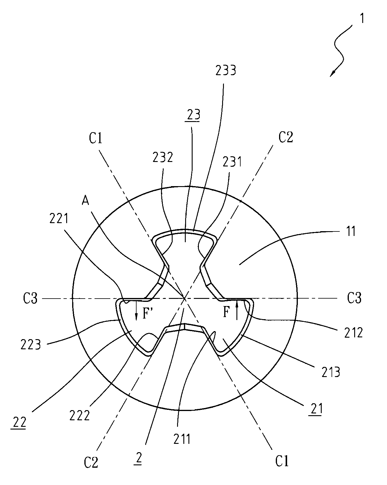
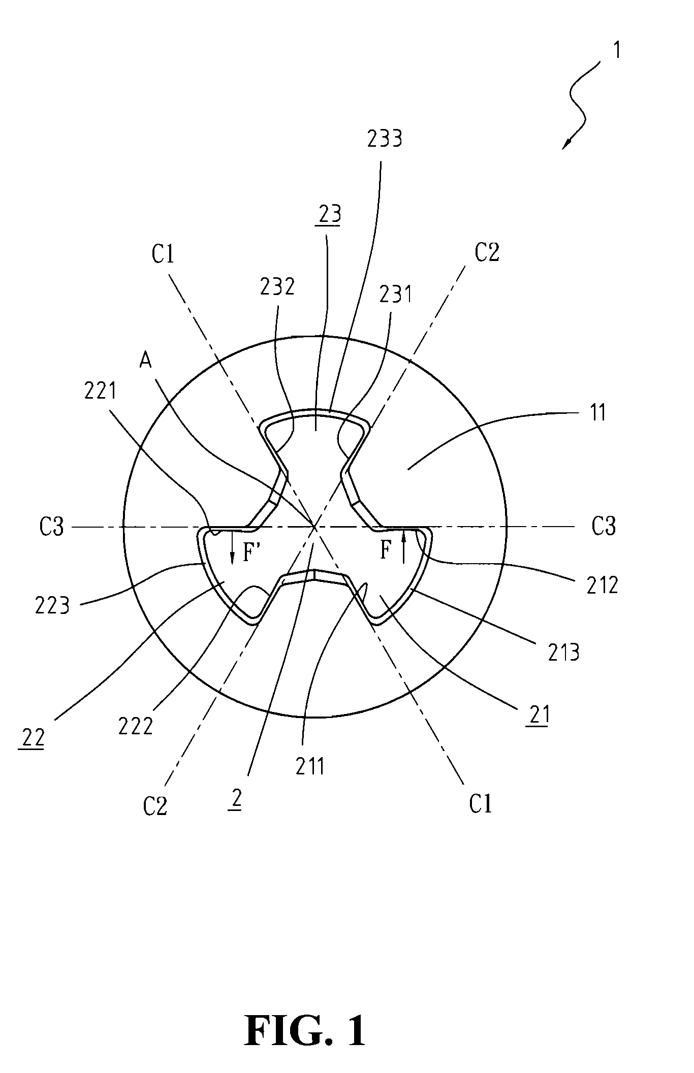
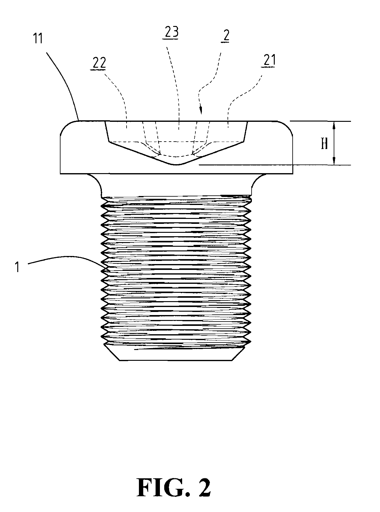
[0019]Referring to FIGS. 1 and 2, diagrams depicting bottom and front views of a screw head recess structure are shown. The screw head recess structure includes a head in any kind of rotational fastener, such as a screw, a bolt and etc., provided with a recess (2) comprised by a plurality of lobular grooves (21) (22) (23), wherein, in a preferred embodiment of the present invention, the three sets of grooves (21) (22) (23) of the recess (2) are arranged in a radiating manner equiangularly from a...


PUM


Abstract

A screw head recess structure and its driving tool that maximizes torque are provided, applicable to any kinds of rotational fasteners, such as screws or bolts. A recess has an irregular shape formed by a plurality of lobular grooves arranged around the center point of a fastener as an axis. A plurality of facets of corresponding grooves along both sides of central lines is formed that receive forces when the fastener rotates clockwise and anticlockwise. As a driving tool having a matching configuration with the recess structure rotates the recess, moment arms of forces and reaction forces exerted upon corresponding facets are on the same central lines, thus maximizing the torque generated by the driving tool. In addition to maximizing the torque, the recess structure is also special in that on which ordinary driving tools cannot operate, thereby protecting the fastener against unwanted disassembly. Moreover, the depth of the recess can be kept shallow since operation of which is effort-saving. This makes the present invention especially suitable for applications that require compact and light fasteners.

Description

FIELD OF THE INVENTION[0001]The present invention relates to a screw head recess structure and its driving tool, and more particularly, to a recess for various kinds of rotational fasteners and the structure and design of a driving tool applicable to the fastener.BACKGROUND OF THE INVENTION[0002]A rotation fastener, such as a screw or a bolt, usually has a particularly shaped recess arranged on the top face of its head for inserting driver bits of a driving tool, such as a screw driver, thereinto and applying forces in a clockwise or anticlockwise fashion in order to tighten or loosen the fastener with respect to an object.[0003]Traditional recess shapes include, for example, linear, crossed, rectangular, or hexagonal shapes. Although such designs are widely used and easy to manufacture, they do not consider the effort required to fasten / unfasten and its convenience. Thus, they have limitations and they as well as their driving tools can be easily damaged. For example, a traditional...

Claims


Application Information

Patent Timeline
Patent Type & Authority Applications(United States)
IPC IPC(8): B25B23/00F16B23/00
CPCF16B23/003B25B15/005
Inventor TSAI, CHUN-HSIN
Owner HAMA NAKA SHOUKIN IND
Why Eureka
Try Eureka