Revolving piston internal combustion engine

a technology of internal combustion engine and rotating piston, which is applied in the direction of rotary piston engine, rotary or oscillating piston engine, engine components, etc., can solve the problems of longer time available for fuel injection into the wankel engine, the inability to pre-store the fuel-air mixture, and the need for more complicated fuel injection technology than for the regular four-stroke engine, so as to reduce the loss, improve the sealing and cooling properties, and reduce vibration.

Inactive Publication Date: 2011-03-03
AMBARDEKAR VISHVAS
View PDF21 Cites 5 Cited by
  • Summary
  • Abstract
  • Description
  • Claims
  • Application Information

AI Technical Summary

Benefits of technology

[0017]The present invention discloses a revolving piston engine for reducing losses associated with conventional reciprocating piston engine, and which further provides easier and improved sealing and cooling properties, lower vibration and reduced power losses properties, in comparison to other prior art rotary piston engine designs.

Problems solved by technology

Corresponding disadvantages of Wankel style engines include, and in comparison to standard four cycle piston engines, the time available for fuel to be injected into the Wankel engine being significantly shorter, and again due to the way the three chambers rotate.
Also, the fuel-air mixture cannot be pre-stored, as there is no intake valve and which means that, in order to obtain acceptable performance out of a Wankel engine, more complicated fuel injection technologies are required than for regular four-stroke engines.
Also, the difference in intake times causes Wankel engines to be more susceptible to pressure loss at low RPM compared to regular piston engines.
Also, and in terms of fuel economy, Wankel engines tend to be generally less efficient than four stroke piston engines.
Problems also occur with exhaust gases at a peripheral port exhaust, where the prevalence of hydrocarbon can be higher than from the exhausts of regular piston engines.
Given the above considerations associated with Wankel engines, appropriate cooling and sealing have become very difficult and probably for these reasons the engine has not become very popular in industries.
Given that gas turbines exhibit very high values of power to weight ratio, and work most efficiently at very high speeds, this renders them for the most part not practical in use with automobiles.

Method used


Image

  • Revolving piston internal combustion engine
  • Revolving piston internal combustion engine
  • Revolving piston internal combustion engine

Examples


Embodiment Construction

[0036]A detailed description of the various embodiments of the present invention will now be provided, beginning with that of the various engine components associated with the revolving piston internal combustion engine. Before proceeding with a detailed description, the following definitions are referenced as relevant to and in cooperation with an explanation of the present inventions, namely:

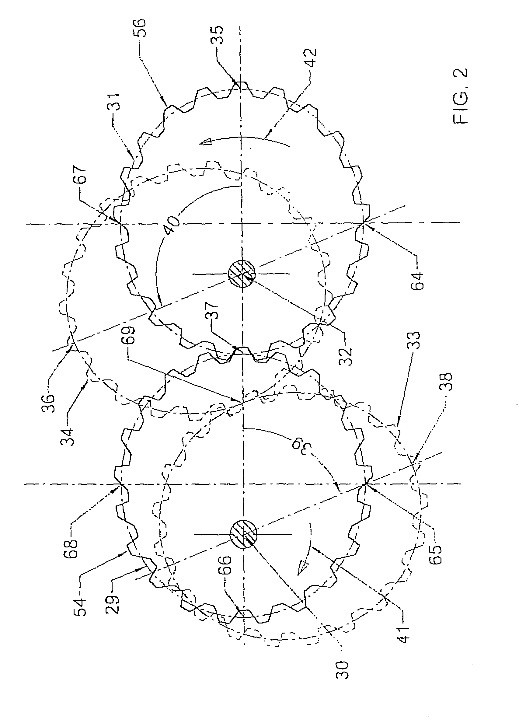
[0037]Pitch ellipse: This is a mathematical ellipse that is used as a base for making an elliptical gear. When two elliptical gears are in meshing engagement, the pitch ellipse(s) corresponds to the respective elliptical gears “roll” over each other. In application, pitch ellipses are used for kinematic calculations.

[0038]Focus of ellipse: There are two such points, on the major axis of every ellipse and which are symmetrical about a minor axis of the ellipse. The summation of the distances from both of its focuses to any point on the ellipse is always equal to the length of its major axis.

Hol...


PUM


Abstract

A revolving piston engine incorporating dual revolving pistons for improving fuel efficiency, increasing power output, easy sealing, easy cooling and reduced vibration. One or more of revolving pistons, each consisting of one piston and one cylinder head, revolve within a ring cylinder, around a common axis in a same direction, but with different velocities. A revolving piston compressor is also disclosed, incorporating appropriately designed and relocated ports / valves for both of associated intake and outlet components.

Description

CROSS-REFERENCE TO RELATED APPLICATIONS[0001]This Application claims the benefit of U.S. Provisional Application 11 / 856,263 filed on Sep. 17, 2007. application Ser. No. 11 / 856,263 is a Continuation-in-part of application Ser. No. 10 / 545,251 filed on Aug. 10, 2005, which is a U.S. National Phase of PCT Application No. PCT / IN02 / 00025 filed Feb. 13, 2003 and entitled “Revolving Piston Internal Combustion Engine”.FIELD OF THE INVENTION[0002]The present invention discloses a revolving piston engine incorporating dual revolving pistons for improving fuel efficiency, increasing power output, easy sealing, easy cooling and reduced vibration. One or more of revolving pistons, each consisting of one piston and one cylinder head, revolve within a ring cylinder, around a common axis in a same direction, but with different velocities. A revolving piston compressor is also disclosed, incorporating appropriately designed and relocated ports / valves for both of associated intake and outlet component...

Claims


Application Information

Patent Timeline
Patent Type & Authority Applications(United States)
IPC IPC(8): F02B53/00F01C1/077
CPCF01C1/077Y02T10/17F02B53/00Y02T10/12
Inventor AMBARDEKAR, VISHVAS
Owner AMBARDEKAR VISHVAS
Why Eureka
Try Eureka