Pull tube sleeve stress joint for floating offshore structure

a stress joint and pull tube technology, applied in the direction of sealing/packing, drilling pipes, well accessories, etc., can solve the problems of increasing the cost of flexible joints, and reducing the service life of the pull tube itself, so as to reduce the stress on the welded connection and increase the section modulus

Active Publication Date: 2011-03-03
TECH FRANCE SA
View PDF5 Cites 7 Cited by
  • Summary
  • Abstract
  • Description
  • Claims
  • Application Information

AI Technical Summary

Benefits of technology

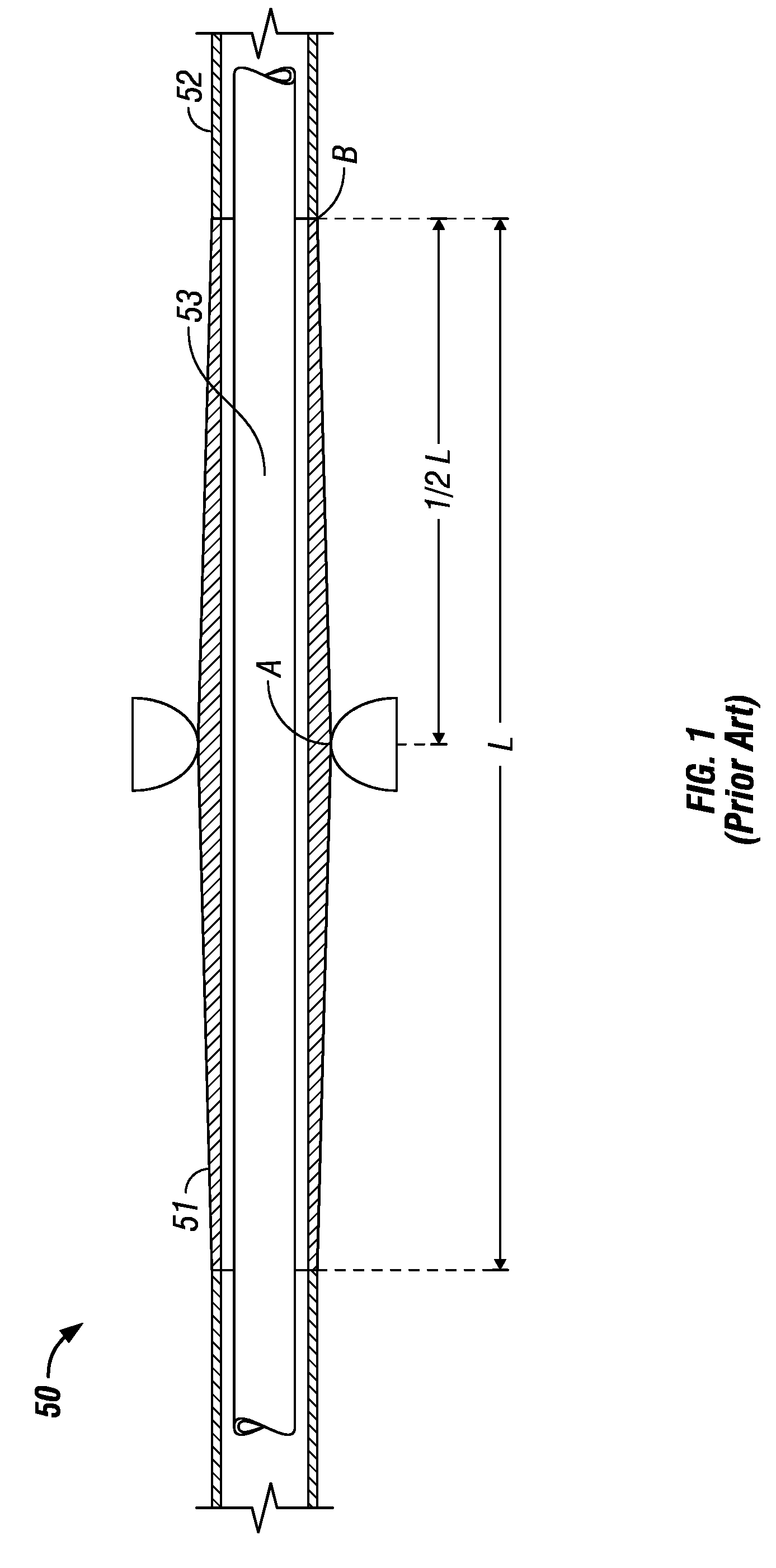
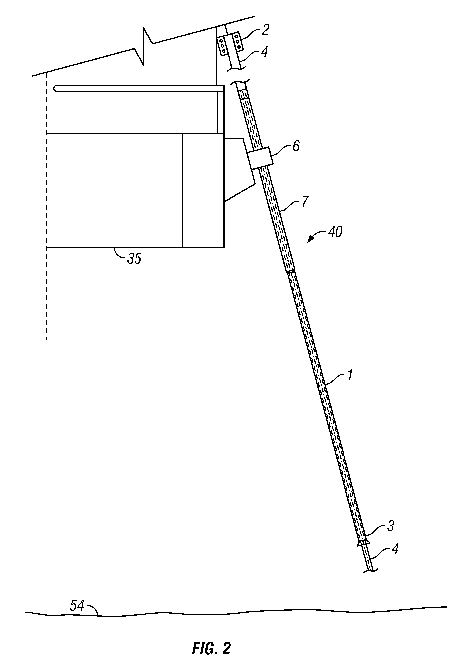
[0012]The present disclosure provides an improved design for a pull tube sleeved stress joint and associated pull tube for managing stresses on a catenary riser for a floating offshore structure. The new design efficiently results in a pull tube sleeved stress joint with at least one sleeve coupled to a pull tube having an annular gap between the outside periphery of the pull tube and the inside periphery of the sleeve with at least one connecting link ring disposed therebetween. For embodiments having a plurality of sleeves, a first sleeve can be spaced by an annular first gap from the pull tube and coupled thereto with a first link ring between the pull tube and the first sleeve, and a second sleeve can be spaced by an annular second gap from the first sleeve and coupled thereto with a second link ring between the first sleeve and the second sleeve. Welded connections between pull tube joints can be longitudinally spaced distally from the sleeve coupled to the pull tube to minimize stresses on the welded connection. Further, a sleeve guide coupled to the offshore structure, and adapted to couple the pull tube and assembly to the offshore structure, can be longitudinally offset by a distance from the link ring and its connections between the pull tube and the sleeve. The design increases a section modulus of the pull tube sleeved stress joint compared to prior efforts at the region of the sleeve guide by placing at least one sleeve on the pull tube and placing a girth weld to adjacent pull tube joints at a zone of lower stress than prior efforts. Thus, the girth welds can be made with a regular weld procedure known as a “F2 Class Weld” instead of the more complex and expensive, and heretofore specified ““C Class Girth Weld”. The design can be adjusted to different performance criteria by changing girth weld locations, length of the sleeve, outside and inside diameters of the sleeve, number of sleeves, spacers between the sleeve and pull tube and between multiple sleeves if any, and other changes. Such changes can be performed at the fabrication yard for the offshore structure and independent of forgings and prefabrication efforts at specialized locations.

Problems solved by technology

However, the flexible joints are more expensive and less reliable than pipe segments that are welded together.
However, the pull tube itself is then stressed and can fail with time.
Such assemblies typically are challenged by fatigue performance at the welds between the segments for the many years in which the SCR will likely be used.
Thus, the challenge is still fatigue performance at the welds between the segments and forging.
Another challenge can be cost and manufacturing schedules specific to a lengthy forging piece.

Method used


Image

  • Pull tube sleeve stress joint for floating offshore structure
  • Pull tube sleeve stress joint for floating offshore structure
  • Pull tube sleeve stress joint for floating offshore structure

Examples


Embodiment Construction

[0028]The Figures described above and the written description of specific structures and functions below are not presented to limit the scope of what Applicant has invented or the scope of the appended claims. Rather, the Figures and written description are provided to teach any person skilled in the art to make and use the inventions for which patent protection is sought. Those skilled in the art will appreciate that not all features of a commercial embodiment of the inventions are described or shown for the sake of clarity and understanding. Persons of skill in this art will also appreciate that the development of an actual commercial embodiment incorporating aspects of the present disclosure will require numerous implementation-specific decisions to achieve the developer's ultimate goal for the commercial embodiment. Such implementation-specific decisions may include, and likely are not limited to, compliance with system-related, business-related, government-related and other con...


PUM


Abstract

The present disclosure provides an improved design for a pull tube sleeved stress joint and associated pull tube for managing stresses on a catenary riser for a floating offshore structure. The pull tube sleeve stress joint includes at least one sleeve surrounding a length of the pull tube with an annular gap between the sleeve and pull tube and a link ring therebetween. For embodiments having a plurality of sleeves, a first sleeve can be spaced by an annular first gap from the pull tube and coupled thereto with a first ring between the pull tube and the first sleeve, and a second sleeve can be spaced by an annular second gap from the first sleeve and coupled thereto with a second ring between the first sleeve and the second sleeve. Both pull tube and sleeves can be made with regular pipe segments welded together with regular girth welds.

Description

CROSS REFERENCE TO RELATED APPLICATIONS[0001]Not applicable.STATEMENT REGARDING FEDERALLY SPONSORED RESEARCH OR DEVELOPMENT[0002]Not applicable.REFERENCE TO APPENDIX[0003]Not applicable.BACKGROUND OF THE INVENTION[0004]1. Field of the Invention[0005]The disclosure generally relates to the production of hydrocarbons from subsea formations. More particularly, the disclosure relates to the risers and related support structures used in such production.[0006]2. Description of the Related Art[0007]In producing hydrocarbons from subsea formations, a number of wells are typically drilled into the sea floor in positions that are not directly below or substantially within the outline of a floating offshore structure, such as a floating offshore production platform. The produced hydrocarbons are subsequently exported via subsea pipelines or other means. Current engineering practice links the offset wells with the offshore structure through risers that have a catenary curve between the structur...

Claims


Application Information

Patent Timeline
Patent Type & Authority Applications(United States)
IPC IPC(8): E21B17/01
CPCE21B19/004
Inventor LUO, MICHAEL Y.H.ZHANG, BOB LIXINCHANG, SHIH-HSIAO MARK
Owner TECH FRANCE SA
Why Eureka
Try Eureka