Cable Transport Device

a technology of transport device and cable, which is applied in the direction of electrical equipment, thin material processing, line/current collector details, etc., can solve the problems of cable threading, cable replacement, and complicated design of force transmission through a plurality of axes of rotation, so as to ensure the necessary precision of cable processing and simplify the design of the cable transport device

Inactive Publication Date: 2011-03-03
SCHLEUNIGER HLDG
View PDF33 Cites 19 Cited by
  • Summary
  • Abstract
  • Description
  • Claims
  • Application Information

AI Technical Summary

Benefits of technology

[0006]It is an object of the invention considerably to simplify the design of a cable transport device having a pivotable cable transporter and in this way to produce said design more economically and nevertheless to ensure the necessary precision for the cable processing.
[0010]With such a design of the cable transport device according to the invention, a very great deal of material can be saved. The number of moving parts is reduced and hence also the susceptibility to faults and the required maintenance.

Problems solved by technology

A disadvantage of this device is, however, the complicated design for force transmission via a plurality of axes of rotation.
Another disadvantage is that the drive motor responsible for the cable transport is arranged directly on the pivot device and must be concomitantly swiveled by the drive motor responsible for the pivoting process.
A guide sleeve in the form of a tube has the disadvantage that it too has to be replaced when changing to a cable having a different cross-section and the cable has to be threaded again.
Such a procedure is complicated and considerably increases the changeover times.

Method used


Image

  • Cable Transport Device
  • Cable Transport Device
  • Cable Transport Device

Examples


Embodiment Construction

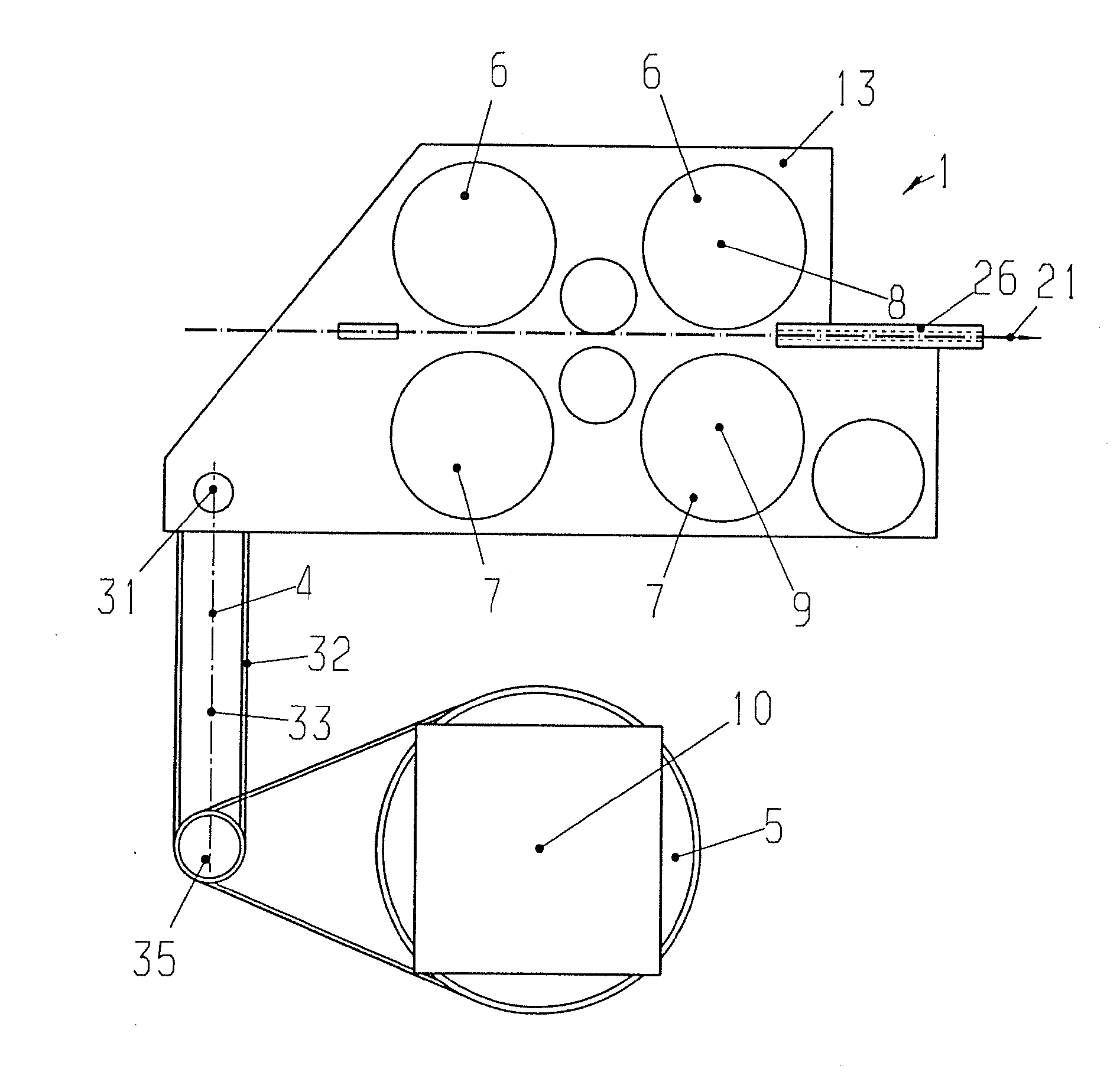
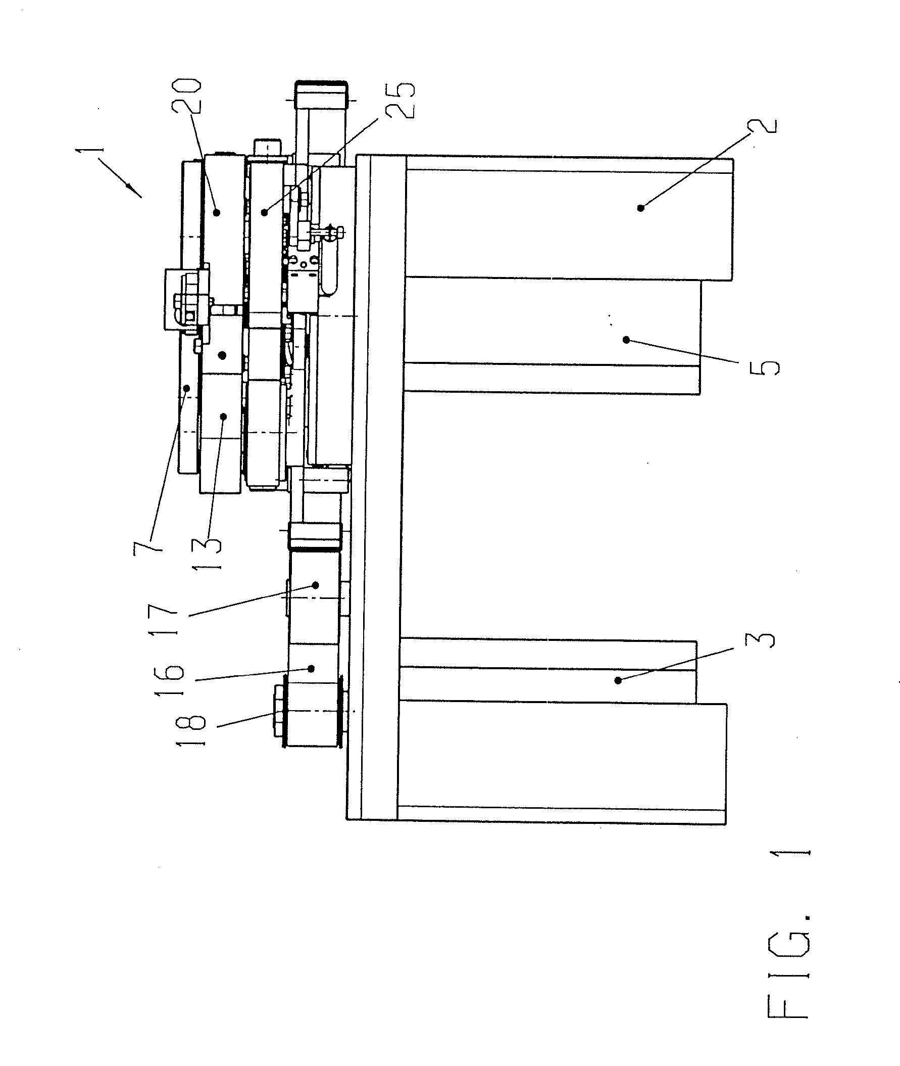
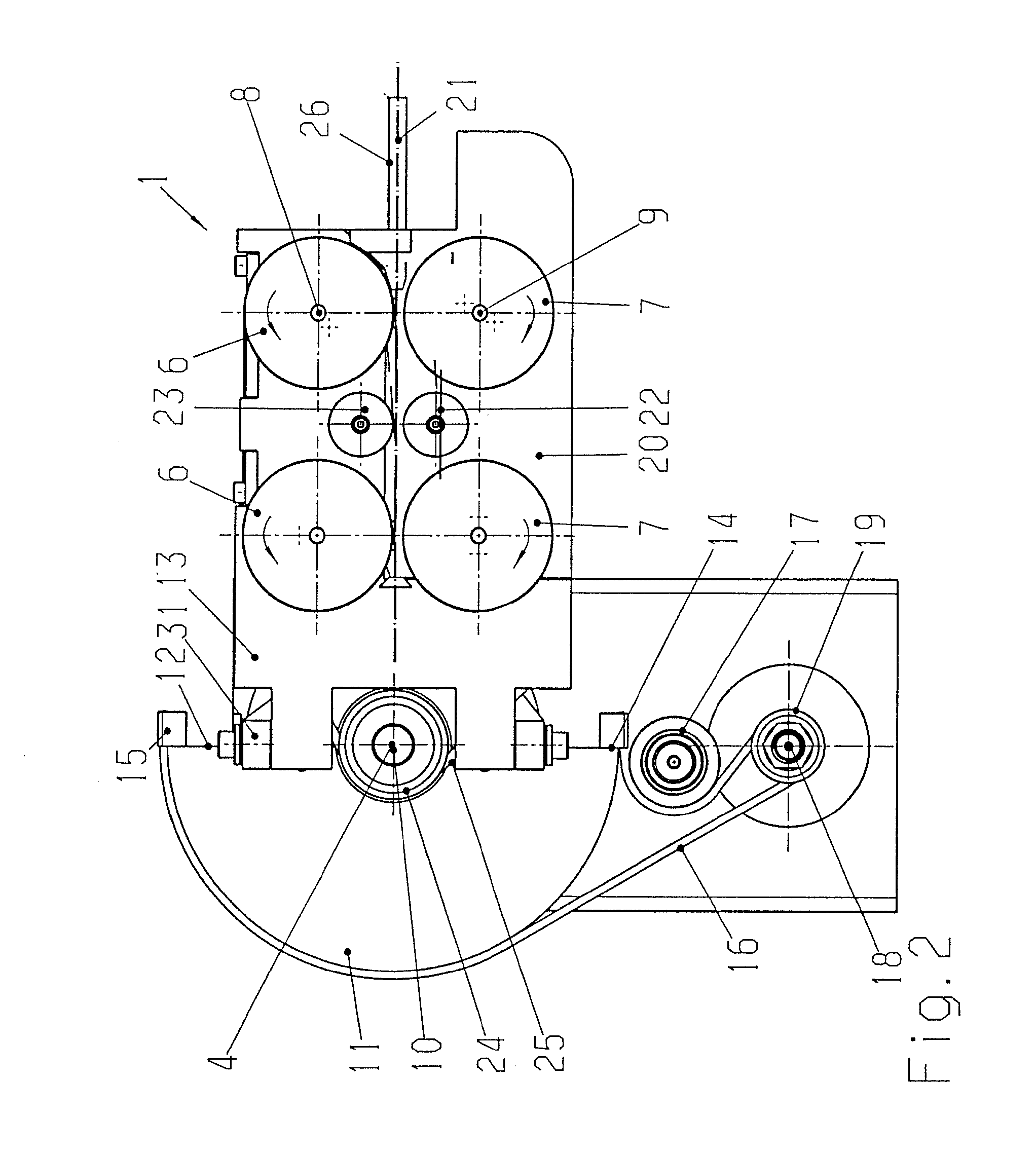
[0026]The cable transport device according to FIGS. 1, 2 and 6 has a pivotably mounted cable transporter 1 for a cable 21 to be drawn in and to be transported, and a first drive means 3 connected in a stationary manner to a base frame 2 and intended for achieving an exactly defined pivot movement of the cable transporter 1 about a pivot axis 4. A second drive means 5 ensures synchronous driving of two cooperating pressure rollers 6 with two cooperating pressure rollers 7, whose axes 8, 9 of rotation are parallel to one another and parallel to the common pivot axis 4. The two pressure rollers 7 are, as shown in FIG. 2, arranged so as to be laterally adjustable.

[0027]According to the invention, the second drive means 5 with its drive axle 10 is connected in a stationary manner to the base frame 2. The drive axle 10 of the second drive means 5 for the pressure rollers 6, 7 of the cable transporter 1, coincides with the pivot axis 4 for the cable transporter 1.

[0028]In the embodiments o...


PUM


Abstract

A cable transport device having a pivotably mounted cable transporter, a first drive means connected in a stationary manner to a base frame and intended for achieving an exactly defined pivot movement of the cable transporter around a pivot axis and a second drive means for synchronous driving of at least two cooperating pressure rollers. The second drive means with a drive axle for the pressure rollers is connected in a stationary manner to the base frame, and the drive axle of the second drive means coincides with the pivot axis for the cable transporter. The transmission of the pivot movement is effected via a toothed belt which is tensioned symmetrically to the center of rotation of the pivot axis between a first intermediate shaft arranged on a base plate of the cable transporter and a second intermediate shaft fixed to the machine frame, the pitch axis of the cable transporter being identical to the axis of the first intermediate shaft.

Description

[0001]The invention relates to a cable transport device having a pivotably mounted cable transporter for a cable to be drawn in and to be transported, a first drive means connected in a stationary manner to a base frame and intended for achieving an exactly defined pivot movement of the cable transporter about a pivot axis and a second drive means for synchronous driving of at least two cooperating pressure rollers, at least one pressure roller being arranged so as to be laterally adjustable, and a cable transport device having a guide sleeve.PRIOR ART[0002]Cable transport devices are known, for example from a CrimpCenter of the applicant. Such cable transport devices are fixed in a stationary manner on a base frame. A first gripper is arranged in the cable transport axis on the base frame on a pivot device having a moveable guide carriage, this gripper cooperating with processing stations, for example with a cutting and insulation stripping station arranged in the cable transport a...

Claims


Application Information

Patent Timeline
Patent Type & Authority Applications(United States)
IPC IPC(8): B65H51/10B65H51/32
CPCB65H51/10B65H51/32B65H57/04H01R43/052B65H2404/1421B65H2701/3911
Inventor SCHÜTZ, PETERWORTMANN, THOMAS
Owner SCHLEUNIGER HLDG
Why Eureka
Try Eureka