
Apparatus for twist-to-lock retention of a wheel

a technology of twist-to-lock and apparatus, which is applied in the direction of release mechanisms, cycle equipment, steering devices, etc., can solve the problems of operator readingjusting the quick-release system, component wear concerns, and almost tightening the skewer for

Active Publication Date: 2011-03-03
HAYES BICYCLE GROUP
View PDF21 Cites 32 Cited by
  • Summary
  • Abstract
  • Description
  • Claims
  • Application Information

AI Technical Summary

Benefits of technology

The invention relates to a quick release assembly engageable with an enclosed dropout fork of a bicycle, wherein the assembly comprises an axle having a first non-cylindrical end portion, a cylindrical central portion, and a second non-cylindrical end portion, wherein a diameter of one of the first non-cylindrical end portion and the second non-cylindrical end portion is larger than the diameter of the cylindrical central portion. The quick release assembly further comprises an insert having a...

Problems solved by technology

Unfortunately, these conventional quick-release retention systems pose a number of problems.
One major problem is that the tightening force on the skewer is almost entirely dependent upon the center distance adjustment made by the user upon installation of the wheel or other component.
It is likely that the adjustments made by the user are inconsistent between different activations of the quick-release retention system, and these inconsistencies can cause possible component wear concerns.
For example, if the center distance is adjusted to be too long, the tightening force may be insufficient, and the component (such as a wheel) may not adequately engage with the fork or bicycle frame, thereby causing the operator to readjust the quick-release system by releasing the quick-release and readjusting the tightening nut.
On the other hand, if the center distance is adjusted to be too short, the axial traction force on the skewer may be too great, thereby risking breakage of the skewer or another element of the quick-release retention system.
Furthermore, an overly-tightened skewer may produce compression forces on the hub bearings of a bicycle wheel, thereby causing substantial friction in the hub and potential early failure of the hub bearings.
It is also common for the repeated tightening of the system to cause wear or galling on the various components, such as the bicycle hub and fork, with each application of the cam.
In view of these potential issues with conventional quick-release retention systems, it is clear that the user-controlled tightening may lead to component wear issues, and at the very least results in substantial trial-and-error by the user in order to achieve the correct tightening force.
Yet another disadvantage related to the conventional quick-release retention systems is that the 9 mm skewers have a cylindrical cross-sectional shape which, when applied with bicycle wheels, are only compatible with fork dropout slots having similarly rounded configurations.
The rough terrain and aggressive, high-speed riding associated with off-ride bicycling leads to substantial torsional forces being exerted on the respective fork legs.
The 20 mm axle configuration, however, is not compatible with the conventional quick-release systems known in the art, and thus the “thru-axle” configuration is typically be secured to the fork using alternative means, such as threaded bolts at each end of the axle.
Such a configuration may necessitate special tools to disengage the wheel from the fork, causing the user to expend a great deal of time and effort.
Furthermore, the 20 mm axle design is over-sized for many applications of off-road bicycling, thereby unduly increasing the weight and cost of the axle systems.

Method used


Image

  • Apparatus for twist-to-lock retention of a wheel
  • Apparatus for twist-to-lock retention of a wheel
  • Apparatus for twist-to-lock retention of a wheel

Examples


Embodiment Construction

A system is shown that provides a quick-release configuration for a wheel, preferably a bicycle wheel. The quick-release configuration uses a twist-to-lock action on a shaft to secure the wheel to a bicycle fork or frame.

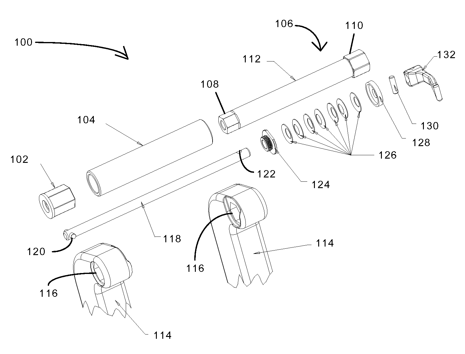
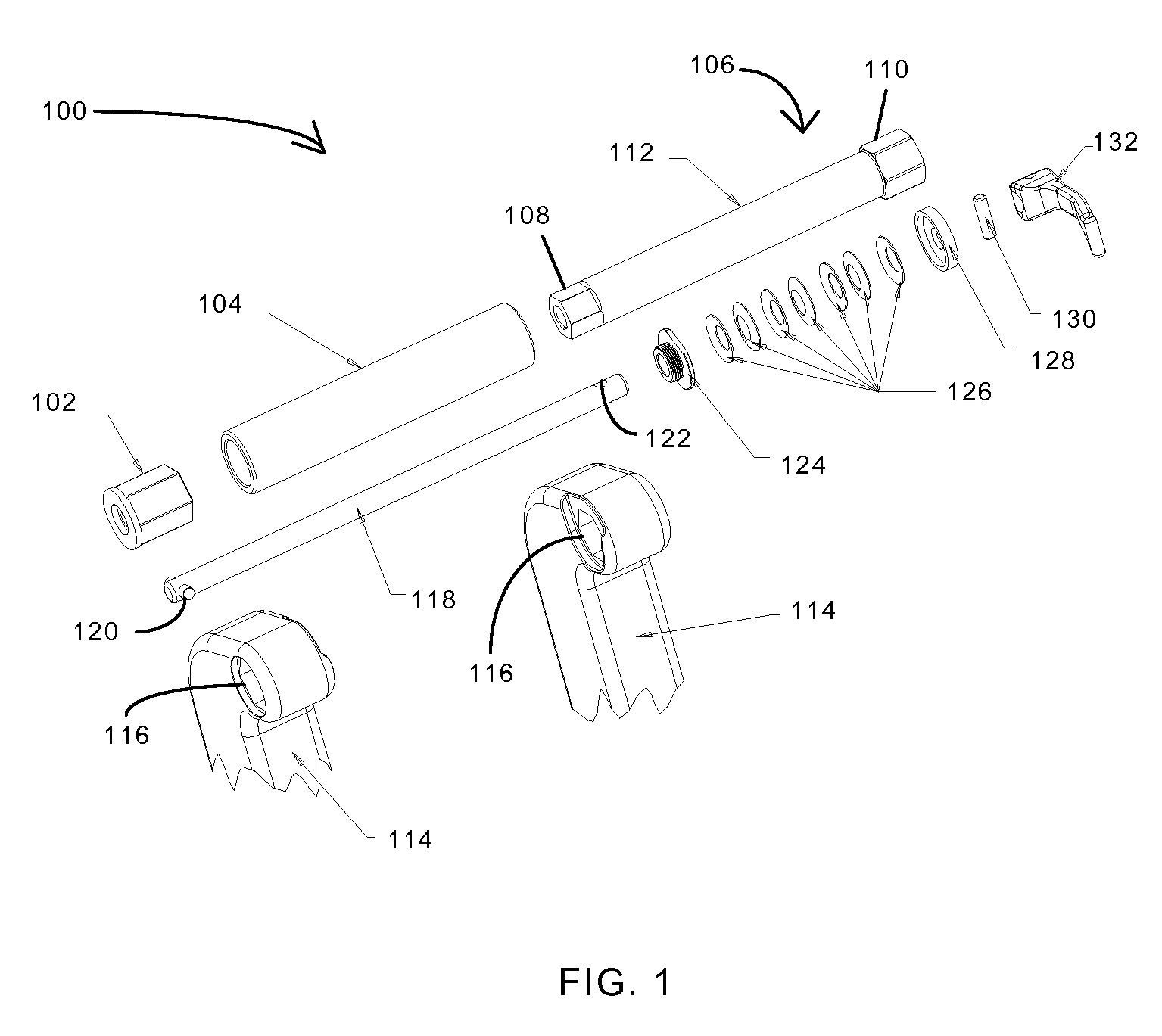
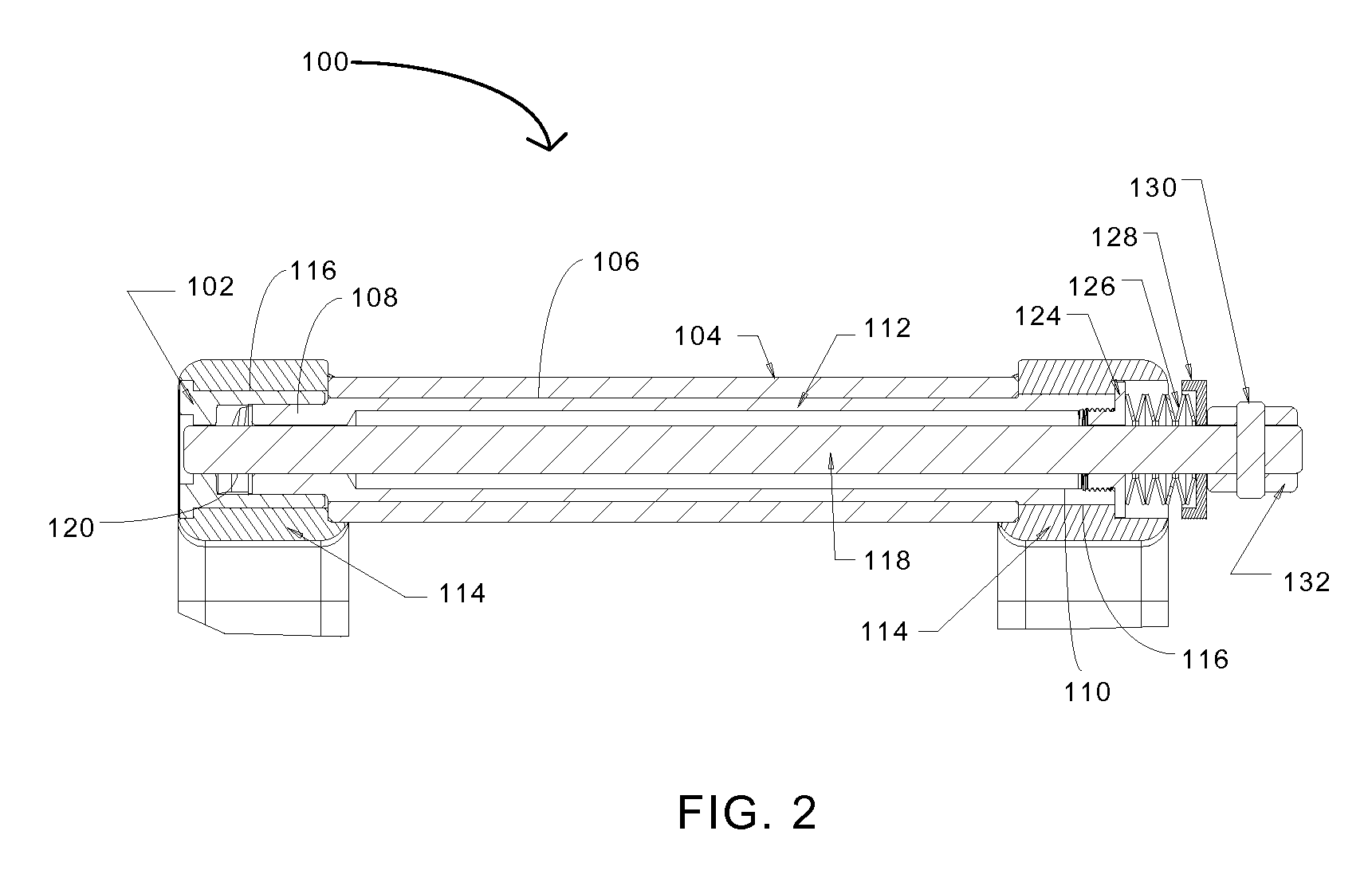
FIG. 1 illustrates an exploded view of an exemplary embodiment of the invention. Quick-release system 100 comprises an insert 102 having a non-cylindrical outer profile, a hub 104, and an axle 106. While not shown, hub 104 comprises a plurality of bearings therein to enable axle 106 to rotate freely when axle 106 is received through a central axis of hub 104. Hub 104 may also be configured to include a plurality of openings to accept wheel spokes therein. Axle 106 is shown having respective non-cylindrical end portions 108, 110 and a cylindrical central portion 112. The diameter of non-cylindrical end portion 110 is larger than that of non-cylindrical end portion 108 and cylindrical central portion 112. In this way, axle 106 is sized to pass through a central axis o...


PUM


Abstract

The invention relates to a quick release assembly for a bicycle, wherein the assembly comprises an axle having a first non-cylindrical end portion, a cylindrical central portion, and a second non-cylindrical end portion, wherein a diameter of one of the non-cylindrical end portions is larger than the diameter of the cylindrical central portion. The quick release assembly further comprises an insert having a non-cylindrical outer profile configured to be retained in a non-cylindrical opening and having a cam surface disposed therein, wherein the insert is sized to retain one of the non-cylindrical end portions of the axle therein. The assembly also includes a shaft sized to pass through the axle and having a cam follower on a first end and a handle on a second end, wherein the cam follower is configured to form a locking engagement with the cam surface upon an axial rotation of the handle.

Description

BACKGROUND OF THE INVENTIONThe present invention relates generally to a quick-release retention system for bicycle wheels or other components, and is more specifically directed to the retention of a wheel using a twist-to-lock configuration for securing a non-cylindrical axle to thru-axle fork dropouts.Quick-release retention systems, particularly for use with bicycles, have been commonplace for many years. These quick-release retention systems allow for rapid connection (or disconnection) of a portion of the bicycle, such as a wheel to a fork, without the need for specialized tools. While the most common application of quick-release devices is for the securing of a bicycle wheel to the fork or frame of the bicycle, quick release devices are also used for other applications, such as securing a bicycle seat post to a seat tube of the bicycle frame.While various types of quick-release retention systems have been devised, the most commonly used of these devices includes a 9 mm threaded...

Claims


Application Information

Patent Timeline
IPC IPC(8): B60B35/00
CPCB60B27/026B60B35/004B60B35/04B60B2310/306B62K2206/00B60B2360/10B60Y2200/13B62K25/02B60B2310/316
Inventor JONES, CHRISTOPHER S.KWATERSKI, EDWARD C.PALLESEN, JOSHUA T.HAGGERTY, JONATHON M.PYE, NICHOLAS W.
Owner HAYES BICYCLE GROUP
Learn More