Organic electroluminescent light source

a light source and electroluminescent technology, applied in the direction of discharge tube luminescnet screens, discharge tube/lamp details, electric discharge lamps, etc., can solve the problem of disadvantageous reduction of light before light emission, and achieve high light extraction efficiency, thin profiles, and high durability

Inactive Publication Date: 2011-03-03
ZEON CORP
View PDF10 Cites 42 Cited by
  • Summary
  • Abstract
  • Description
  • Claims
  • Application Information

AI Technical Summary

Benefits of technology

[0038]The light source device of the present invention has high light extraction efficiency and can have high durability even though they have simple and thin profiles. Therefore, the light source device is useful as a backlight for a liquid crystal display and a light source for, e.g., a lighting device.

Problems solved by technology

Specifically, even though the luminescent layer of the organic EL element itself has high light-emitting efficiency, the amount of light can be disadvantageously reduced before the light emission as the light passes through the multilayer structure that constitutes the element, due to, for example, interference in the layers.

Method used


Image

  • Organic electroluminescent light source
  • Organic electroluminescent light source
  • Organic electroluminescent light source

Examples


first embodiment

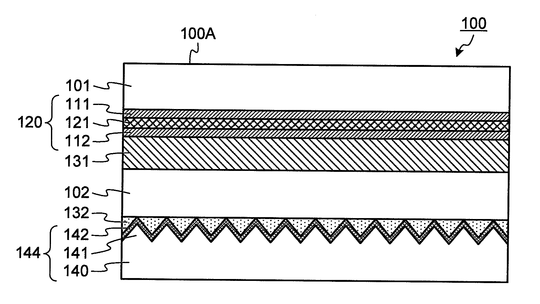
[0061]FIG. 1 is a vertical cross-sectional view illustrating the layer configuration of an organic EL light source device according to a first embodiment of the present invention. In the present application, unless otherwise specified, light source devices will be described with the luminescent layer of the device extending horizontally and with the light-emitting surface of the device facing up. Therefore, in the following description, unless otherwise specified, a “horizontal plane” is a plane parallel to the principal surface of the luminescent layer; the upper side of the light source device is the light-emitting surface side; and the lower side is the side opposite to the light-emitting surface.

[0062]In FIG. 1, the device 100 includes: a substrate 101; a luminescent element 120 provided on the lower side of the substrate 101; a sealing substrate 102 provided on the lower side of the luminescent element 120 via a sealing layer 131; and a reflecting member 144 bonded to the lower...

second embodiment

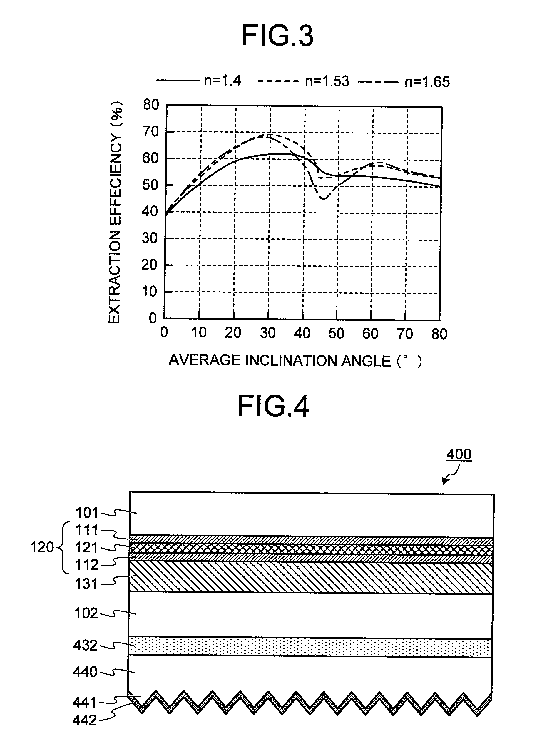
[0107]FIG. 4 is a vertical cross-sectional view illustrating the layer configuration of an organic EL light source device according to a second embodiment of the present invention. The device 400 shown in FIG. 4 is different from the device in the first embodiment in that the device 400 includes: a transparent concavo-convex layer 440 provided on the lower side of the sealing substrate 102 via a bonding layer 432; a concavo-convex structure 441 provided on the lower surface of the transparent concavo-convex layer 440; and a reflecting layer 442 provided on the lower surface of the concavo-convex structure 441. In the present embodiment shown in FIG. 4, since the reflecting layer 442 is provided along the concavo-convex structure 441 of the transparent concavo-convex layer 440, the reflecting layer 442 may thereby have a specific concavo-convex structure that is specified in the present invention. Therefore, such a configuration can also achieve an improved light extraction efficienc...

third embodiment

[0109]FIG. 5 is a vertical cross-sectional view illustrating the layer configuration of an organic EL light source device according to a third embodiment of the present invention. The present embodiment is a further modification of the second embodiment shown in FIG. 4. The device 500 shown in FIG. 5 is different from the device in the second embodiment in that the device 500 includes: concavo-convex structure 541 made of a transparent resin and provided directly on the lower surface of the sealing substrate 102 without a boding layer interposed therebetween; and a reflecting layer 542 provided along the concavo-convex structure 541. Also with this configuration, the reflecting layer 542 is configured to have the concavo-convex structure specified in the present invention. Therefore, the light extraction efficiency can be improved with satisfying the requirements of the present invention, to achieve the desired effects.


PUM


Abstract

An organic electroluminescent light source device includes, in the following order from a light-emitting surface side, a first transparent electrode layer, a luminescent layer, a second transparent electrode layer, and a reflecting layer, wherein the reflecting layer includes a concavo-convex structure with an average inclination angle of 12 to 45°. An organic electroluminescent light source device includes, in the following order, a first transparent electrode layer, a luminescent layer, a second transparent electrode layer, a diffusing layer, and a reflecting-scattering layer, wherein the diffusing layer has a concavo-convex surface including a concavo-convex structure with an average inclination angle of 17 to 45°.

Description

TECHNICAL FIELD[0001]The present invention relates to an organic electroluminescent (which may be abbreviated hereinbelow as “organic EL”) light source device.BACKGROUND ART[0002]An organic EL light source device (which may be referred to as an organic EL device) is a device that has an organic luminescent layer between a plurality of electrodes to achieve electrical luminescence. Organic EL elements are contemplated to be used as display elements as an alternative to liquid crystal cells. In addition, the organic EL elements are also contemplated to be used as surface light sources such as flat lighting devices and the backlights for liquid crystal displays, taking advantage of the characteristics such as high luminescence efficiency, low driving voltage, light weight, and low cost.[0003]When an organic EL device is used as a surface light source, it is necessary to extract light from the organic EL device in a useful form at high efficiency. Specifically, even though the luminesce...

Claims


Application Information

Patent Timeline
Patent Type & Authority Applications(United States)
IPC IPC(8): H01J1/62
CPCH01L51/5237H01L51/5271H01L51/5268H10K50/841H10K50/854H10K50/856
Inventor INOUE, HIROYASUTANIMOTO, HIROTOSHI
Owner ZEON CORP
Why Eureka
Try Eureka