Electro-optical device and electronic apparatus

a technology of optical devices and electronic devices, applied in the direction of discharge tubes, discharge tubes, instruments, etc., can solve the problems of difficult to realize frame narrowing, difficult to secure reliability, and required frame narrowing

Active Publication Date: 2011-03-03
ELEMENT CAPITAL COMMERCIAL CO PTE LTD
View PDF9 Cites 373 Cited by
  • Summary
  • Abstract
  • Description
  • Claims
  • Application Information

AI Technical Summary

Benefits of technology

[0023]Accordingly, it is possible to provide the electro-optical device capable of realizing both reliability securing and frame narrowing.
[0024]Since the display panel has a flexibility capable of being bent substantially at a right-angle, it is possible to realize frame narrowing which was potentially and highly required as a market demand.
[0025]Accordingly, it is possible to suggest a valid application of the electro-optical device utilizing the flexibility. In other words, it is possible to provide an electro-optical device capable of realizing frame narrowing utilizing the flexibility.

Problems solved by technology

On the other hand, as the market demands, frame narrowing has been required.
However, in a display device of the related art, it is difficult to realize frame narrowing.
In detail, since there is a trade-off between frame narrowing and reliability securing, it is difficult to secure reliability if the frame region is short and frame narrowing is not realized if a predetermined length of the frame region is secured.
In other words, in the display device of the related art, it is difficult to secure reliability and narrow the frame compatibly.
Even when the display device has flexibility, since the frame region is not decreased due to flexibility, it is difficult to narrow the frame.
If the frame region is long, the frame region is an obstacle even when tiling is performed.
Thus, it is difficult to realize a seamless display and to obtain sufficient display quality.
Accordingly, it is difficult to take advantage of the flexibility.

Method used


Image

  • Electro-optical device and electronic apparatus
  • Electro-optical device and electronic apparatus
  • Electro-optical device and electronic apparatus

Examples


embodiment 1

Overview of Display Device

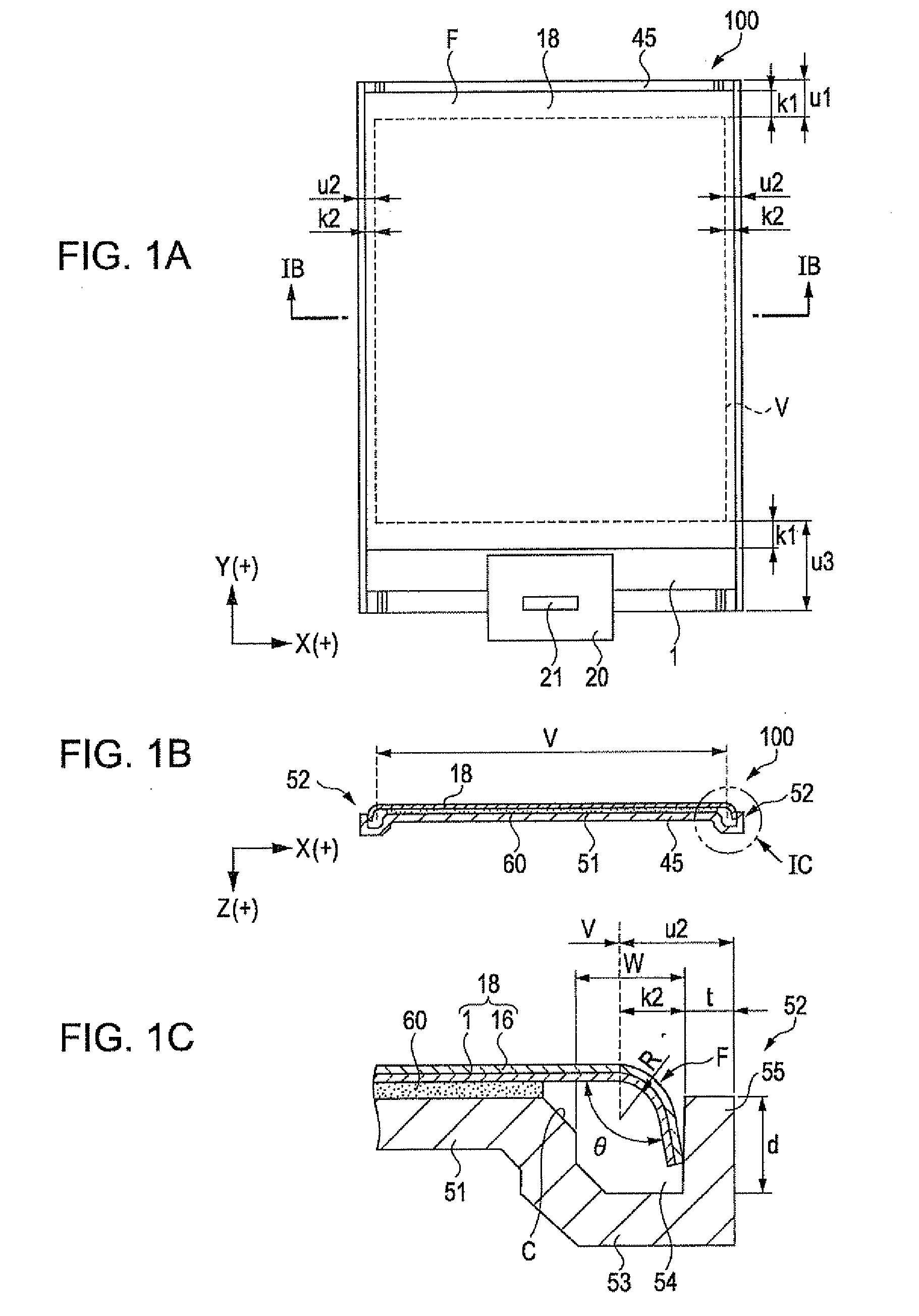
[0068]FIG. 1A is a plan view showing a display device according to the present embodiment, FIG. 1B is a side cross-sectional view taken along line IB-IB, and FIG. 1C is an enlarged view of an IC portion of FIG. 1B.

[0069]First, the overview of the display device 100 as an electro-optical device according to Embodiment 1 of the invention will be described.

[0070]The display device 100 is a thin organic EL display device and includes a support frame 45 and a display panel 18 set on the support frame. The display panel 18 is an organic EL panel obtained by interposing an organic EL layer between a pair of glass substrates made sufficiently thin and has a flexibility capable of being bent substantially at a right-angle. In addition, the thickness or the flexibility of the glass substrate will be described later.

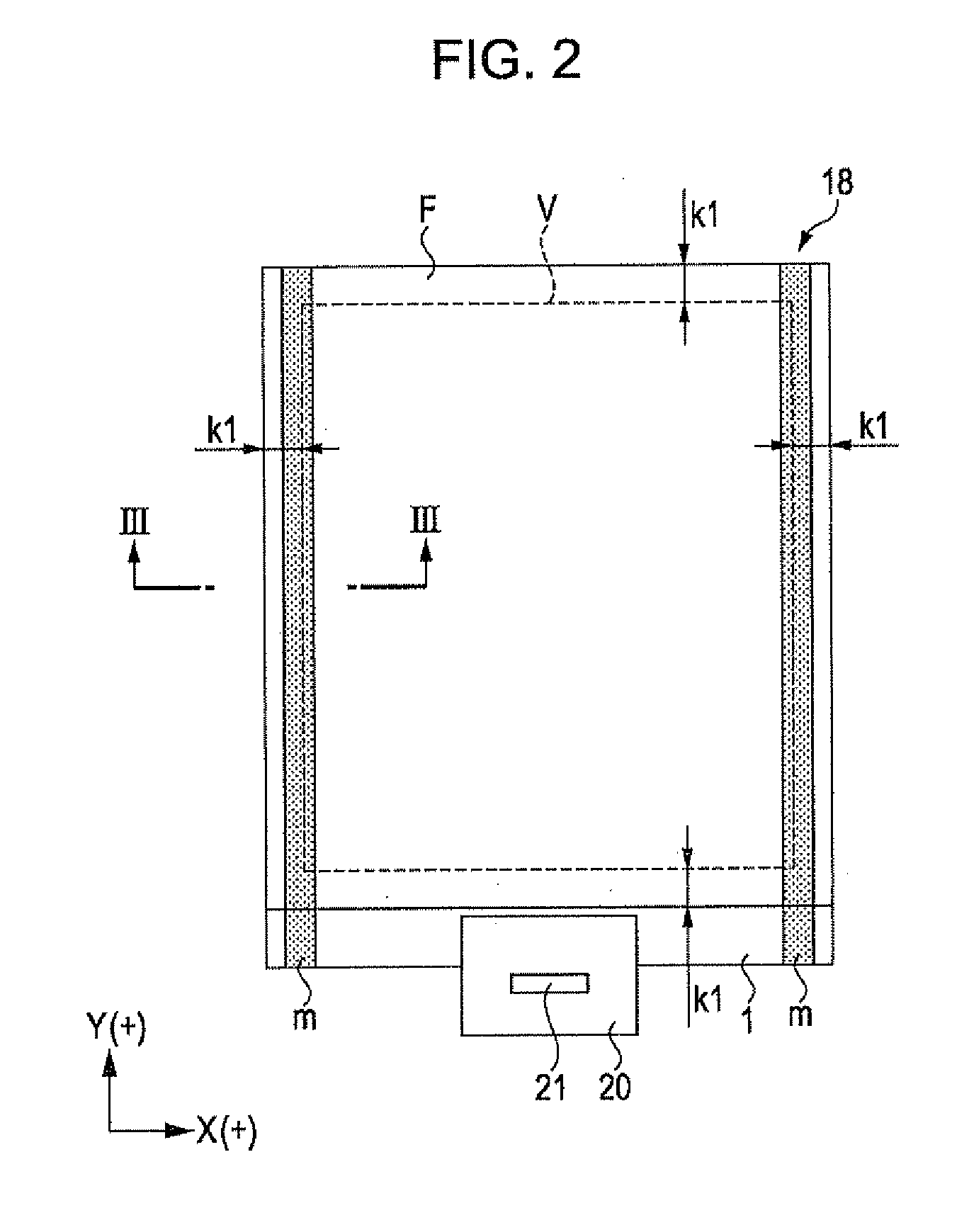
[0071]The display panel 18 includes a display region V including a plurality of pixels arranged in a matrix. In the display region V, color pixels of red ...

embodiment 2

[0178]FIG. 6A is a plan view showing a display device of Embodiment 2, FIG. 6B is a side cross-sectional view taken along line VIB-VIB of FIG. 6A, and FIG. 6C is an enlarged view of a VIC portion of FIG. 6B. FIGS. 6A to 6C correspond to FIGS. 1A to 1C, respectively. FIG. 7A is a plan view of a display panel, which corresponds to FIG. 2.

[0179]Hereinafter, a display device 110 according to Embodiment 2 of the invention will be described. In addition, the same components as Embodiment 1 are denoted by the same reference numerals and the description thereof will be omitted.

[0180]The display device 110 of the present embodiment is a display device capable of realizing frame narrowing, by employing a structure in which the left and right frame regions are folded back using a display panel 28 having a structure in which a display panel 19 obtained by increasing the horizontal width of the display panel 18 of Embodiment 1 is laminated by resin films from the front and rear surfaces thereof....

embodiment 3

Outline of Display Device

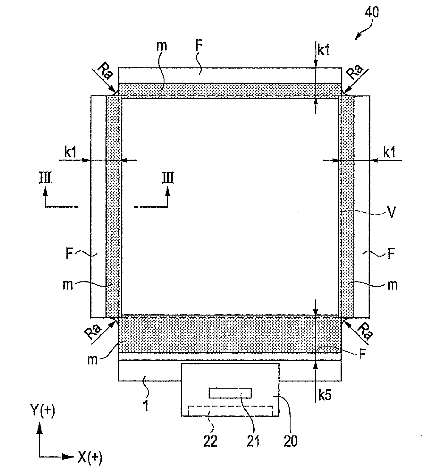
[0259]FIG. 9A is a plan view showing a display device of Embodiment 3, FIG. 9B is a side cross-sectional view taken along line IXB-IXB of FIG. 9A, and FIG. 9C is an enlarged view of an IXC portion of FIG. 9B.

[0260]Hereinafter, the outline of the display device 120 as an electro-optical device according to Embodiment 3 will be described. In addition, the same components as Embodiments 1 and 2 are denoted by the same reference numerals and the description thereof will be omitted.

[0261]The display device 120 of the present embodiment is a display device suitable for a tiling use, which is capable of realizing frame narrowing throughout all circumferences by using a structure in which the frame region of all the four sides of the display region V are bent.

[0262]The display device 120 is an organic EL display device and includes a support frame 50 and a display panel 40 set on the support frame.

[0263]The display panel 40 is an organic EL panel which is equal to t...


PUM


Abstract

An electro-optical device includes a display panel obtained by forming an electro-optical layer, in which a plurality of pixels is formed, on a glass substrate having a thickness of 50 μm or less; and a support frame supporting the display panel, wherein the display panel has at least a display region in which the plurality of pixels is formed and frame regions formed outside the display region, and wherein at least one side of each of the frame regions is bent from the vicinity of a circumference of the display region to the support frame side and is fixed to the support frame.

Description

CROSS REFERENCES TO RELATED APPLICATIONS[0001]The present invention contains subject matter related to Japanese Patent Application No. 2009-193940 filed in the Japanese Patent Office on Aug. 25, 2009 and Japanese Patent Application No. 2009-193941 filed in the Japanese Patent Office on Aug. 25, 2009, the entire contents of which are incorporated herein by reference.BACKGROUND[0002]1. Technical Field[0003]The present invention relates to an electro-optical device and an electronic apparatus including the electro-optical device.[0004]2. Related Art[0005]Since an organic electroluminescent (EL) display device which is a self-light emitting device is easily made thin as compared with a liquid crystal display device requiring an illumination device such as a backlight, various applications utilizing thinness and lightness have been proposed.[0006]For example, in JP-A-2005-19082, an organic EL display device in which an organic EL layer is interposed between two glass substrates made thin...

Claims


Application Information

Patent Timeline
Patent Type & Authority Applications(United States)
IPC IPC(8): G09G3/30H05K7/00H01J1/62G09G5/00
CPCH01L27/3293H04M1/0266H01L2251/5338H01L51/5237H10K59/18H10K2102/311H10K59/87H10K50/84
Inventor YAMADA, TADASHI
Owner ELEMENT CAPITAL COMMERCIAL CO PTE LTD
Why Eureka
Try Eureka