
Lens unit and imaging device

Inactive Publication Date: 2011-03-03
SHARP KK
View PDF19 Cites 0 Cited by
  • Summary
  • Abstract
  • Description
  • Claims
  • Application Information

AI Technical Summary

Benefits of technology

[0027]As is apparent from the above, according to the present invention, a small sized and high-performance lens unit is realized.
[0028]Also, according to the present invention, by including the lens unit that is space-saving and is superior in optical characteristics, a small sized and high-performance imaging device is realized.

Problems solved by technology

However, the lens unit having the zoom function has the following problems.
Thus, it is difficult to shorten the lens unit, and the optical design needs to take it into consideration to provide this space.
(5) If a small amount of resin is applied and molded so as not to generate a resin protrusion 73, poor molding occurs due to resin un-filling.

Method used


Image

  • Lens unit and imaging device
  • Lens unit and imaging device
  • Lens unit and imaging device

Examples


first embodiment

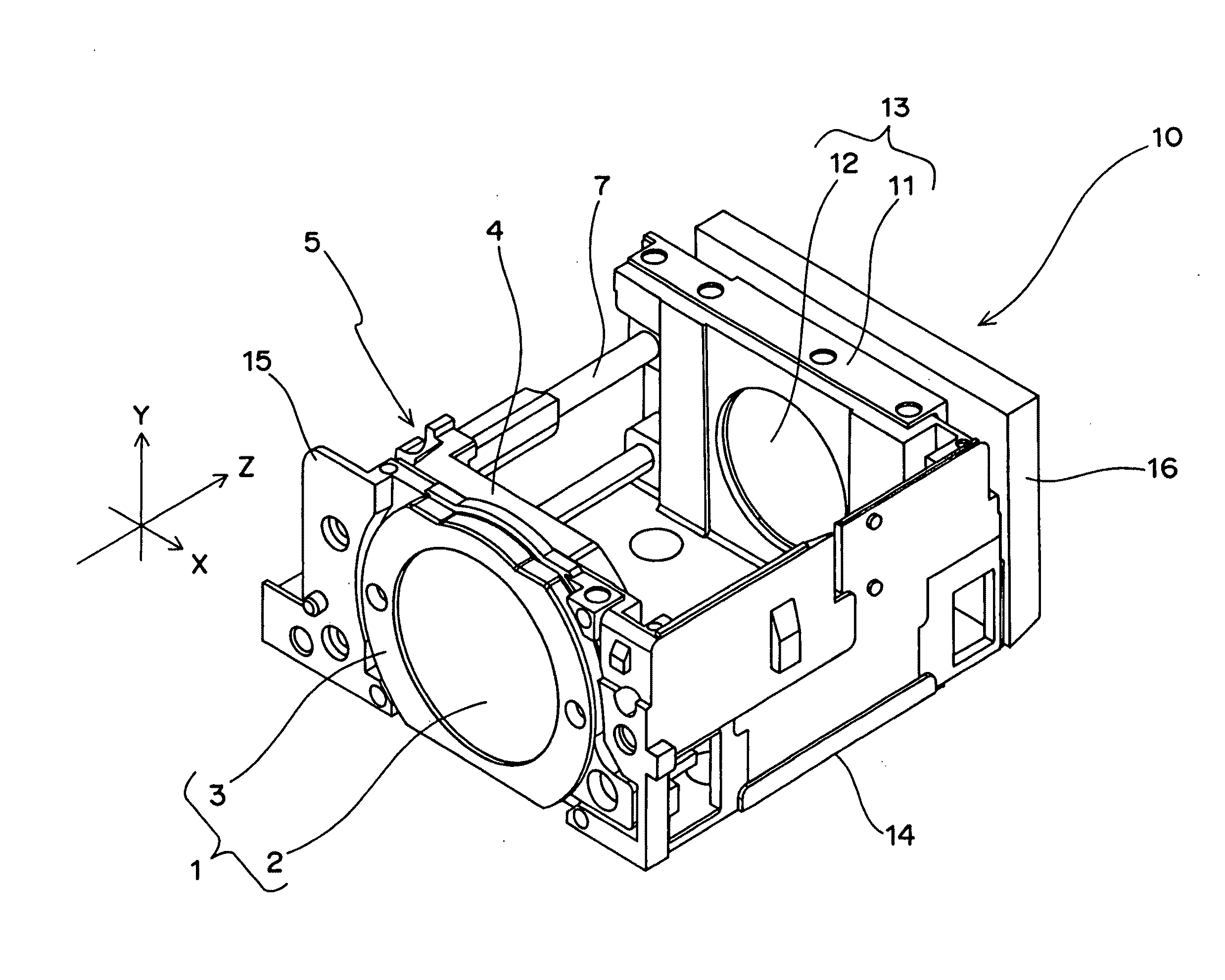
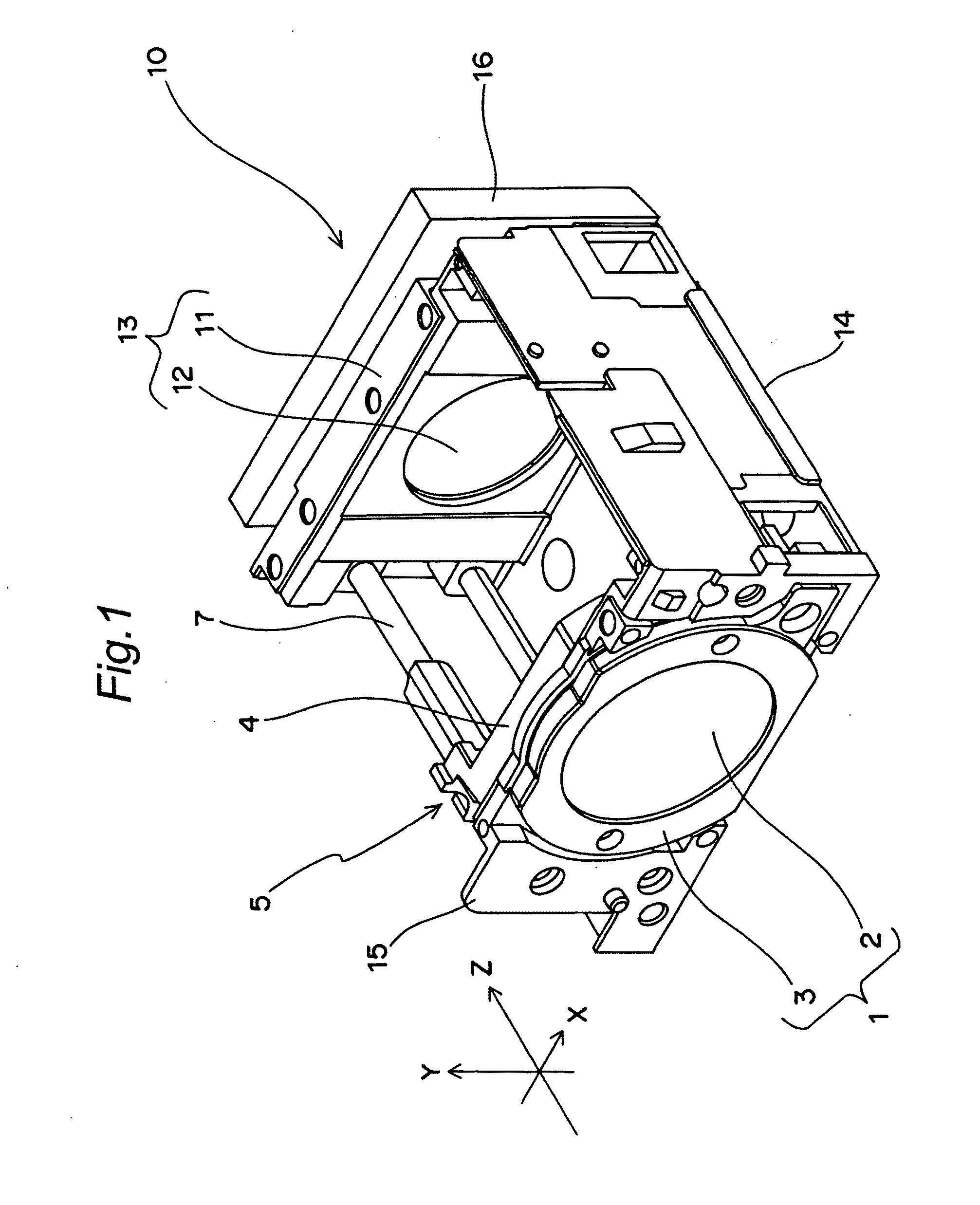
[0041]FIG. 1 is a perspective view of a lens unit according to the first embodiment of the present invention.

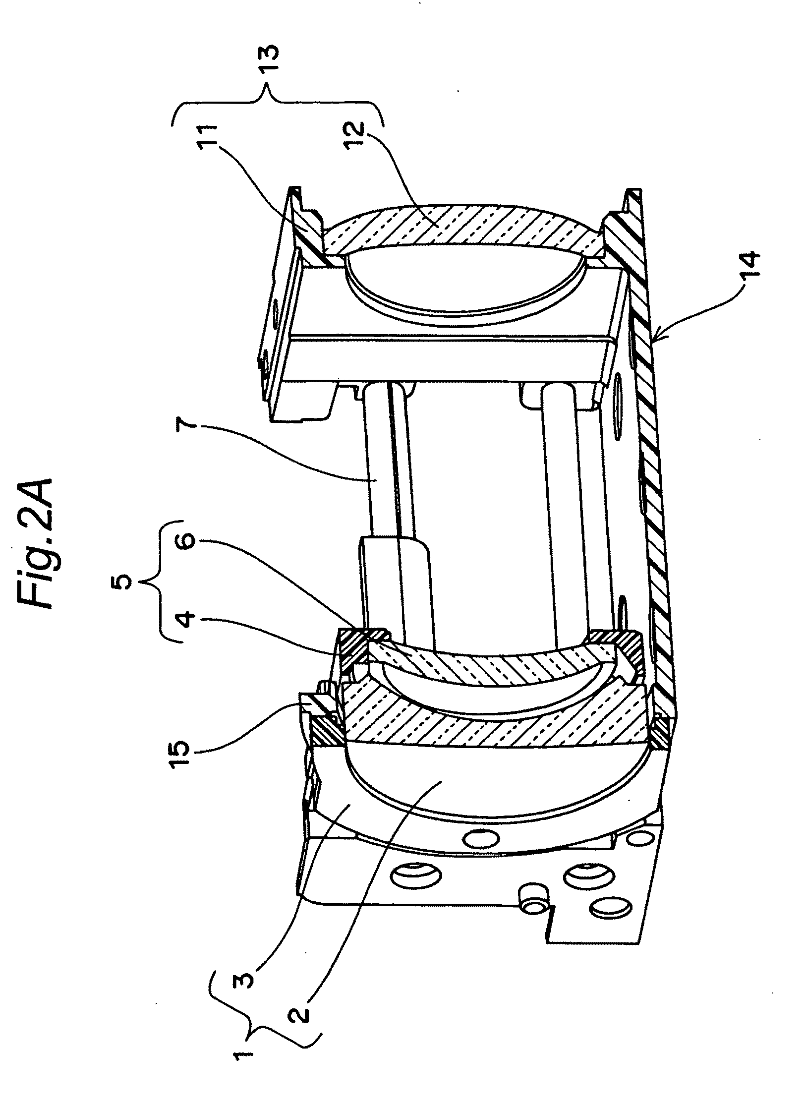
[0042]Here, the direction of a Z-axis is defined as the direction of an optical axis, while the direction of an X-axis and the direction of a Y-axis are defined as the directions of extension of a plane parallel to an imaging surface. The imaging surface has been set on an imaging element 16. FIG. 2A shows a Z-Y section of the lens unit 10 shown in FIG. 1 seen from the direction of the X-axis.

[0043]As shown in FIGS. 1 and 2A, the lens unit 10 has a base 14 shaped like a substantially rectangular plate parallel to the X-Z plane, a first lens group fixing section 15 which is installed at a subject-side end of the base 14 in an upright manner in parallel with the X-Y plane that is substantially normal to a plane of the base 14, and a third lens holder 11 which is installed at an imaging surface-side end of the base 14 in an upright manner in parallel with the X-Y plane substanti...

second embodiment

[0067]FIG. 6 is a perspective view of a lens unit according to the second embodiment of the present invention. The lens unit of this embodiment is the same in configuration as the lens unit of the first embodiment, except for a third lent unit 120. Here, the direction of a Z-axis is defined as the direction of an optical axis, while the direction of an X-axis and the direction of a Y-axis are defined as the directions of extension of a plane parallel to an imaging surface. The imaging surface has been set on an imaging element 116. FIG. 7A shows a Z-Y section of the lens unit 110 shown in FIG. 6 seen from the direction of the X-axis.

[0068]As shown in FIGS. 6 and 7A, the lens unit 10 has a base 114 shaped like a substantially rectangular plate parallel to the X-Z plane, a first lens group fixing section 115 which is installed at a subject-side end of the base 114 in an upright manner in parallel with the X-Y plane that is substantially normal to a plane of the base 114, and a fourth ...


PUM


Abstract

A lens unit having a first lens (2) whose optical surface on the imaging surface side is made of resin (32), a first lens holder (3) for holding the first lens (2), a second lens (6) placed to the imaging side of and spaced in the optical axis direction from the first lens (2), and a second lens holder (4) for holding the second lens (6). The first lens (2) and the second lens (6) are movable relative to each other. A second lens holder recess (8) which a resin projection (33) of the first lens (2) can enter and exit from is formed in the second lens holder (4).

Description

TECHNICAL FIELD[0001]The present invention relates to a lens unit and an imaging device and in particular to a small lens unit and an imaging device using the lens unit.BACKGROUND ART[0002]A conventional lens unit has a zoom function of driving two or more lens groups in the direction of an optical axis, as shown in FIG. 8 (see JP 2003-270509 A, for example). In FIG. 8, an imaging element is in the positive direction of the Z-axis, and a subject is in the negative direction of the Z-axis.[0003]The lens unit having a zoom function shown in FIG. 8 has a first lens holder 51 holding a first lens group 50 and a second lens holder 53 holding a second lens group 52. The first lens holder 51 is guided in the direction of the optical axis (Z-axis) along a first guide shaft 54. The second lens holder 53 is guided in the direction of the optical axis along a second guide shaft 55. In this way, the first and second lens holders 51 and 53 can be moved in the direction of the optical axis along ...

Claims


Application Information

Patent Timeline
IPC IPC(8): H04N5/225G02B7/02
CPCG02B7/102H04N5/2257H04N5/2254H04N23/57H04N23/55
Inventor NISHIKAWA, MASAYUKIFUJITA, HIDEAKI
Owner SHARP KK
Learn More