Projector

a projector and projector body technology, applied in the field of projectors, can solve the problems of increasing the size of the device, increasing the manufacturing cost, increasing the number of elements, etc., and achieve the effect of cost reduction

Inactive Publication Date: 2011-03-03
SEIKO EPSON CORP
View PDF3 Cites 10 Cited by
  • Summary
  • Abstract
  • Description
  • Claims
  • Application Information

AI Technical Summary

Benefits of technology

[0005]An advantage of some aspects of the invention is to provide a projector in which the two light modulation devices can be provided to each of the single l...

Problems solved by technology

However, in such measures, there arise problems of, for example, growth in size of the device and increase in ...

Method used


Image

  • Projector
  • Projector
  • Projector

Examples


first modified example

2-1. First Modified Example

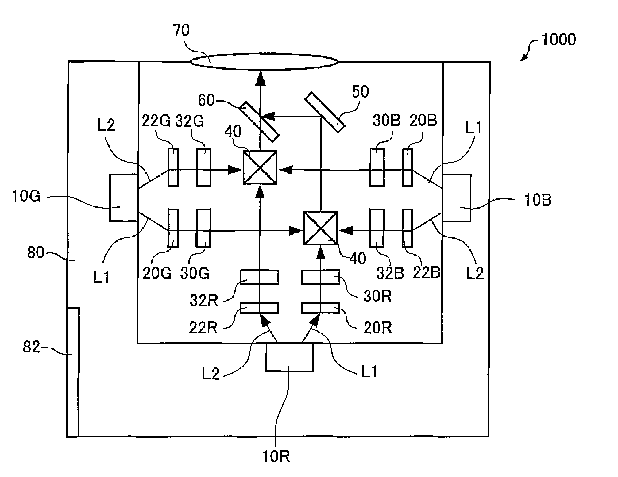
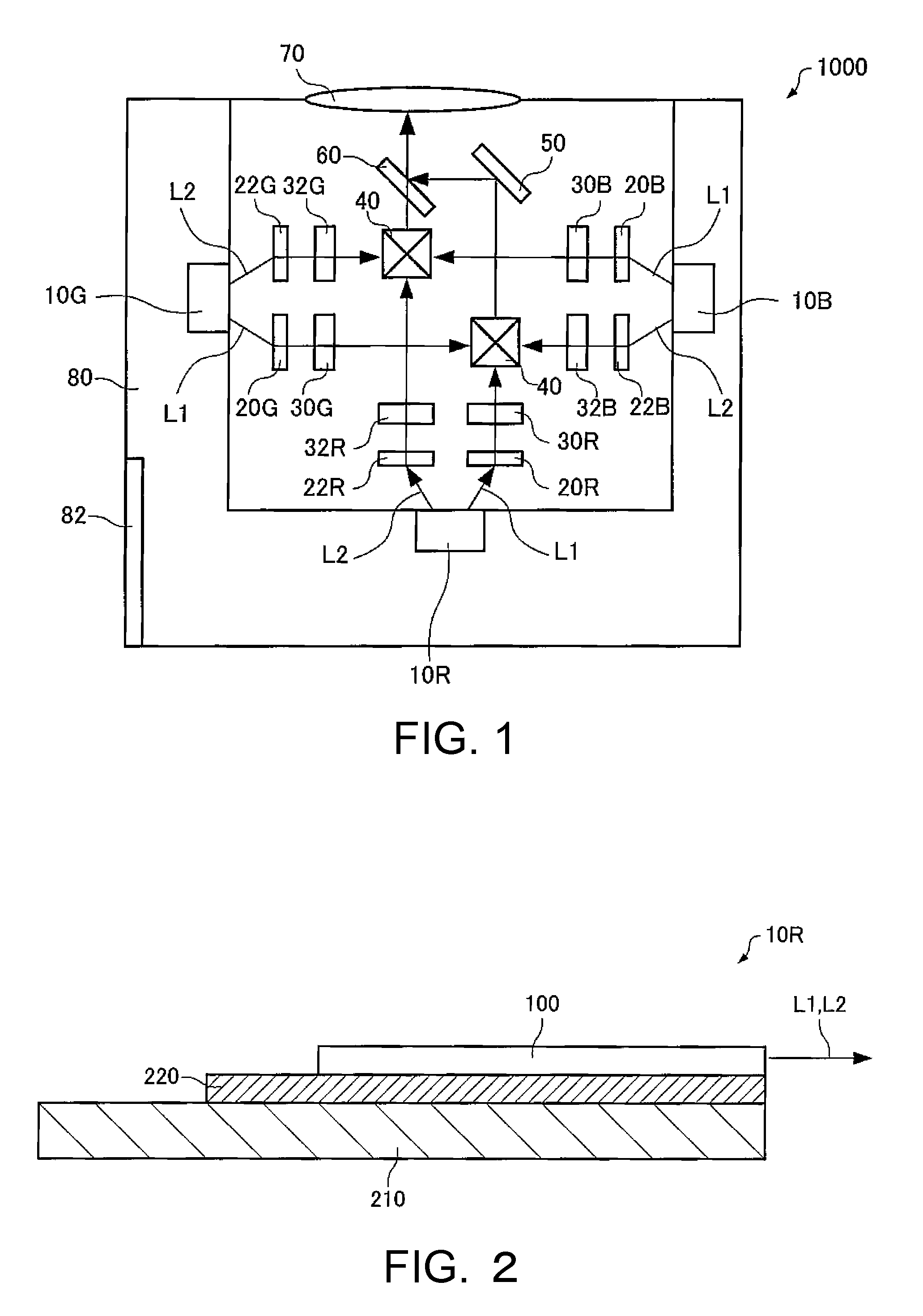
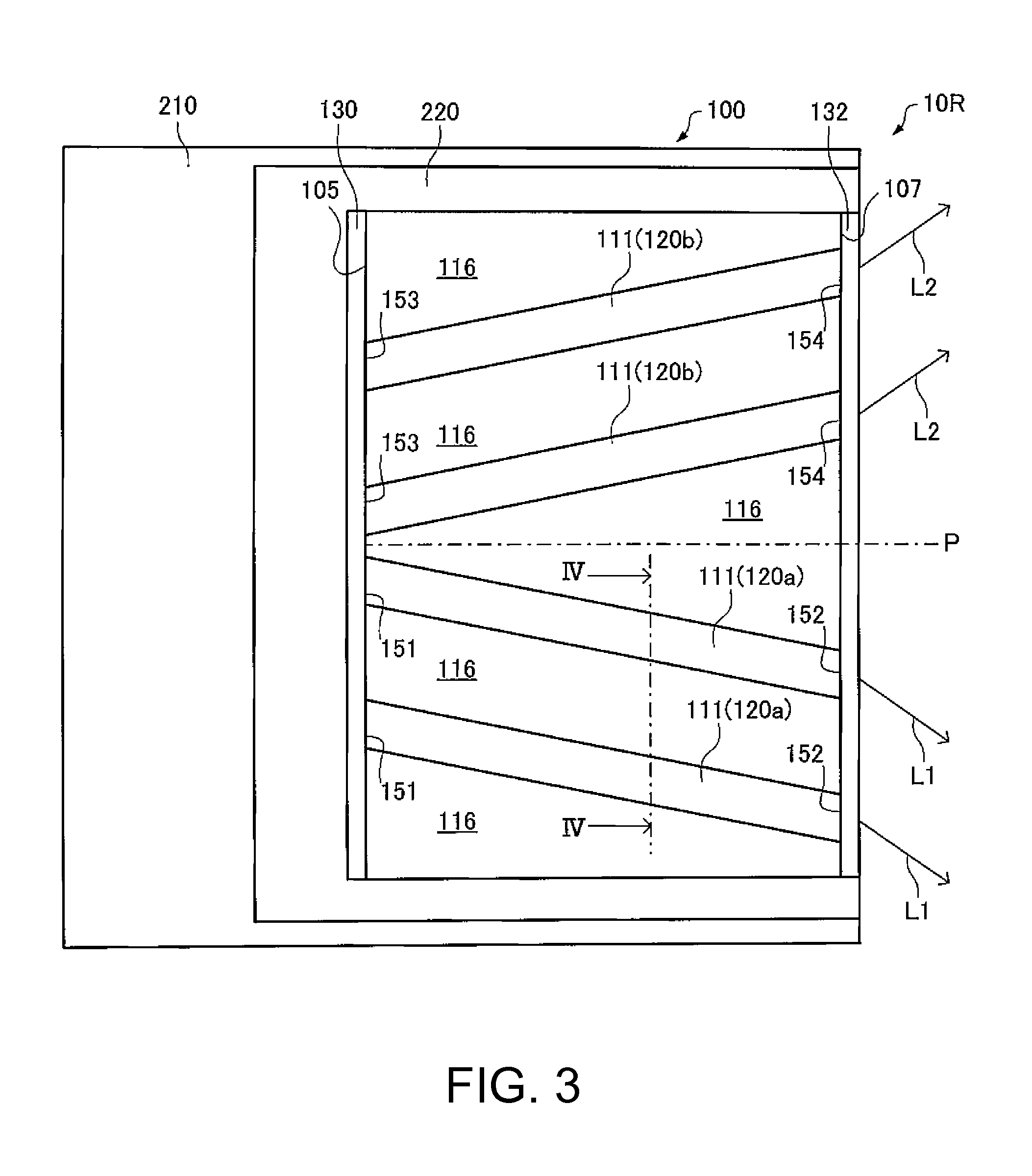
[0072]Firstly, a first modified example will be explained. In the example of the projector 1000, the case of using the light emitting devices 10R, 10G, and 10B as the light sources, each having the light emitting element 100 in which the first and the second gain regions 120a, 120b having different tilt angles with respect to the perpendicular P are arranged is explained. In the projector according to the present modified example, there can be used light emitting devices 12R, 12G, and 12B as the light sources, each having a light emitting element 300 in which gain regions 120 having the same tilt angles with respect to the perpendicular P are arranged. Hereinafter, the light emitting device 12R for emitting the red light will be explained as a representative of the light emitting devices 12R, 12G, and 12B. FIG. 5 is a cross-sectional view schematically showing the light emitting device 12R. FIG. 6 is a plan view of the light emitting device 12R. It should ...

second modified example

2-2. Second Modified Example

[0080]Then, a second modified example will be described hereinafter. FIG. 7 is a diagram schematically showing a projector 2000 according to the present modified example.

[0081]In the projector 2000, the first diffractive optical elements 20R, 20G, and 20B and the second diffractive optical elements 22R, 22G, and 22B disposed with respect to the light emitting devices 10R, 10G, and 10B can be integrated, respectively. For example, the first and the second diffractive optical element 20R, 22R disposed with respect to the red light emitting device 10R can be integrated. The same can be applied to the green and the blue light emitting device 10G, 10B. Thus, since the number of components can be reduced, cost reduction and downsizing can be achieved.

[0082]In the projector 2000, the first light modulation devices 30R, 30G, and 30B and the second light modulation devices 32R, 32G, and 32B disposed with respect to the light emitting devices 10R, 10G, and 10B are ...


PUM


Abstract

A projector includes: at least one light emitting device having a light emitting element adapted to emit a first outgoing light and a second outgoing light proceeding in a direction different from a direction of the first outgoing light; a first light modulation device adapted to modulate the first outgoing light in accordance with image information; a second light modulation device adapted to modulate the second outgoing light in accordance with image information; and a projection device adapted to project the light modulated by the first light modulation device and the light modulated by the second light modulation device, wherein the light emitting element is a super luminescent diode provided with a stacked structure having an active layer sandwiched between a first cladding layer and a second cladding layer, and the active layer has a first emission surface adapted to emit the first outgoing light and a second emission surface adapted to emit the second outgoing light.

Description

BACKGROUND[0001]1. Technical Field[0002]The present invention relates to a projector.[0003]2. Related Art[0004]Recent years, laser elements with high luminance and superior in color reproducibility have become promising light emitting devices for light sources of projectors (see, e.g., JP-A-2009-75151). In the projectors using such light emitting devices, there is a known structure of providing two light modulation devices (e.g., light valves) to each of a red light source (the light emitting device), a blue light source (the light emitting device), and a green light source (the light emitting device) in order to realize a 3D projector. Such two light modulation devices for each color are also used for doubling the resolution of the image projected. In the case of providing the two light modulation devices to the light source of emitting each colored light, as a measure for inputting the light to each of the two light modulation devices, there can be cited, for example, a measure of...

Claims


Application Information

Patent Timeline
IPC IPC(8): G03B21/28G03B21/14
CPCH04N9/3105H04N9/3161H04N9/3164G03B21/2066G03B21/2033G03B21/14H04N9/3197G03B33/12
Inventor MOCHIZUKI, MASAMITSU
Owner SEIKO EPSON CORP
Why Eureka
Try Eureka