
Article having metal dielectric reflective film

Inactive Publication Date: 2011-03-03
HON HAI PRECISION IND CO LTD
View PDF3 Cites 6 Cited by
  • Summary
  • Abstract
  • Description
  • Claims
  • Application Information

AI Technical Summary

Problems solved by technology

However, reflection wavelength range of current reflective films is unsatisfactorily wide, such as 400 nm to 650 nm, resulting in colorful reflection.

Method used


Image

  • Article having metal dielectric reflective film
  • Article having metal dielectric reflective film
  • Article having metal dielectric reflective film

Examples


example 1

[0017]Material, refractive index and thickness of each layer of the metal dielectric reflective film 10 of Example 1 are shown in Table 1, wherein the d=λ / (4n), λ=600 nm.

TABLE 1RefractiveLayersMaterialindexThickness (d)Thickness (nm)First layerAl2O31.657600.1920781769.53Second layerSi3N41.783010.2183322973.47Third layerAl2O31.657600.2465346689.24Fourth layerSi3N41.783010.2366648479.64Metal layerCr3.427320.017136583.00

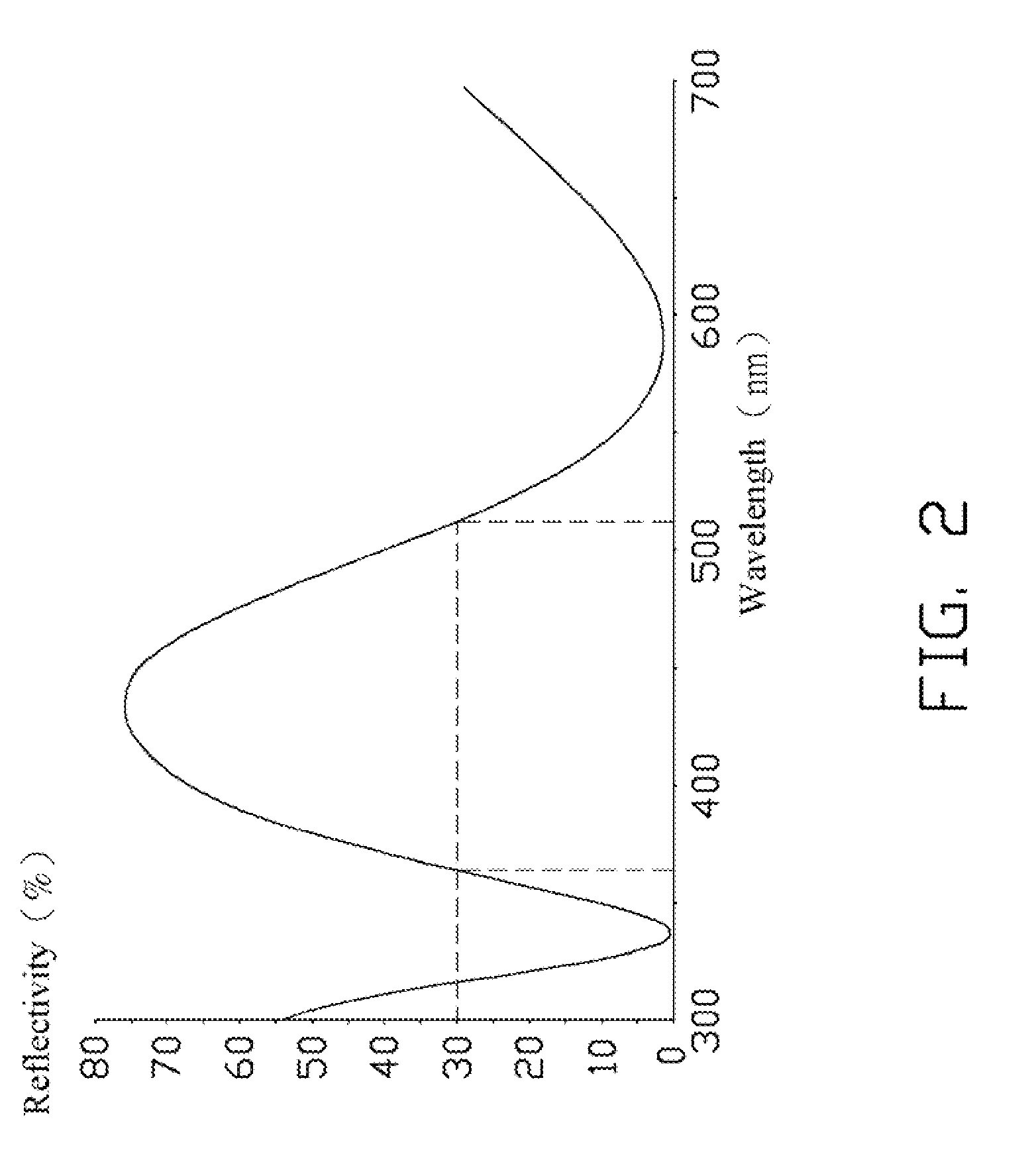
[0018]Reflection wavelength reflected by the metal dielectric reflective film 10 of Example 1 and the reflectivity is over 30%, is in the range from about 480 nm to about 650 nm.

example 2

[0019]Material, refractive index and thickness of each layer of the metal dielectric reflective film 10 of Example 1 are shown in Table 1, wherein the d=λ / (4n), λ=490 nm.

TABLE 2RefractiveLayersMaterialindexThickness (d)Thickness (nm)First layerAl2O31.658070.1920781756.76Second layerSi3N41.804550.2183322959.28Third layerAl2O31.658070.2465346672.86Fourth layerSi3N41.804550.2366648464.26Metal layerCr2.488560.015236063.00

[0020]Reflection wavelength reflected by the metal dielectric reflective film 10 of Example 1 and the reflectivity is over 30%, is in the range from about 400 nm to about 540 nm.

[0021]Although reflection wavelength range of Example 1 and Example 2 are different with each other, the reflection wavelength ranges are narrowly. Therefore, reflection color saturation of the metal dielectric reflective film 10 of Example 1 and Example 2 are relatively better.


PUM


Abstract

A article includes a substrate and a metal dielectric reflective film. The metal dielectric reflective film is formed on the substrate, the metal dielectric reflective film includes a dielectric multiple layer and a metal layer. The dielectric multiple layer includes a first layer, a second layer, a third layer, and a fourth layer arranged in the order written and stacked one on another. The first and third layers comprised of a low refractive index material, the second and fourth layers comprised of a high refractive index material. The metal layer is disposed on the fourth layer.

Description

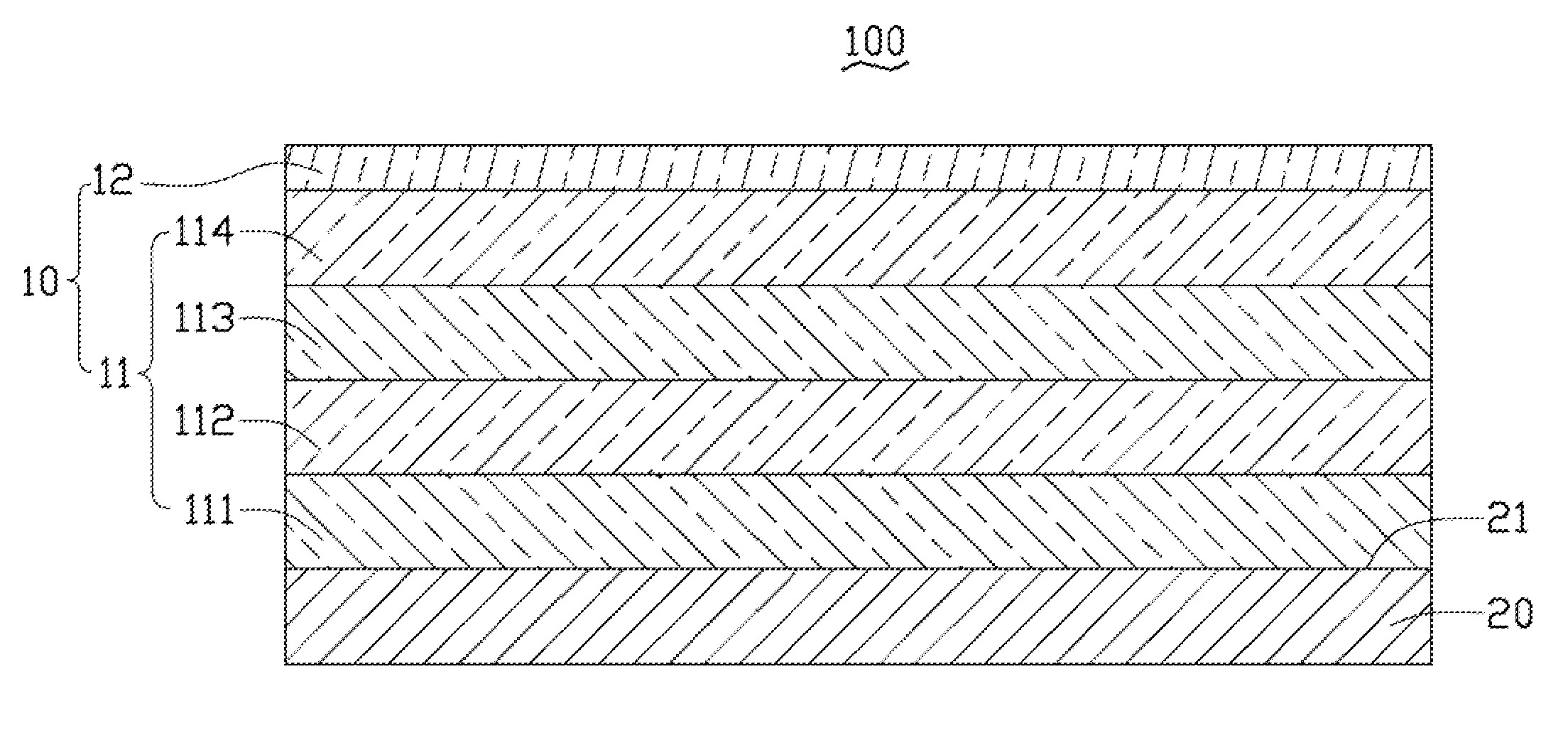
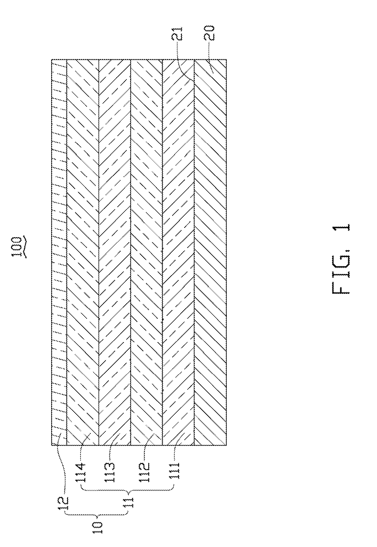
BACKGROUND[0001]1. Technical Field[0002]The present disclosure relates to reflective films and, particularly, to an article having a metal dielectric reflective film.[0003]2. Description of Related Art[0004]Reflective films have been extensively applied to articles to enhance the reflectivity of the articles. However, reflection wavelength range of current reflective films is unsatisfactorily wide, such as 400 nm to 650 nm, resulting in colorful reflection.[0005]Therefore, an article having the metal dielectric reflective film which can overcome the above-described problems is desirable.BRIEF DESCRIPTION OF THE DRAWINGS[0006]FIG. 1 is a cross-sectional, schematic view of an article in accordance with an embodiment.[0007]FIG. 2 is a graph showing reflection characteristics of the article having the metal dielectric reflective film of FIG. 1.[0008]FIG. 3 is a graph showing reflection characteristics of three different metal dielectric reflective films.DETAILED DESCRIPTION[0009]Embodim...

Claims


Application Information

Patent Timeline
IPC IPC(8): G02B1/10
CPCG02B5/0858
Inventor HUANG, CHIEN-HAO
Owner HON HAI PRECISION IND CO LTD
Learn More