Modular rotor assembly

a technology of rotors and components, applied in the field of modular rotor assemblies, can solve the problems of increasing assembly costs, laborious and therefore expensive, requiring precision fabrication of all components, and requiring greater storage costs, so as to save the need for individual component alignmen

Inactive Publication Date: 2011-03-03
INGERSOLL RAND CO
View PDF27 Cites 2 Cited by
  • Summary
  • Abstract
  • Description
  • Claims
  • Application Information

AI Technical Summary

Benefits of technology

[0006]There is provided a modular pre-assembly of some components of a drive into a carrier. In accordance with an embodiment of the present invention, a carrier is precision machined to accept drive components in an aligned condition to each other for quick assembly into the gearbox housing. Portions of the drive system for a piece of rotating equipment are pre-assembled into a subassembly. The subassembly can be held together by a carrier that is fabricated to accept the components in a proper alignment so that the carrier can be installed as a unit. In one embodiment, the carrier becomes a gearbox housing component that is installed, saving the need for individual component alignment. This modular approach allows an assembly having a single part number to apply to a given compressor unit and further allows standardization of air ends of compressors with specific impellers and inlets added to meet requirements of a specific application.

Problems solved by technology

Assembling these components for every unit is labor intensive and therefore expensive.
This requires greater costs for storage, proper inventory and, most of all, in assembly costs for a given unit.
Another costly issue is the need to precision fabricate all the components to facilitate the alignment procedure.
The individual part tolerances can add up, making the ultimate alignment more difficult.
A failure to properly control alignment can result in premature bearing, seal, or gear set wear.
Manually assembling and aligning each unit can be a significant portion of the total labor cost.

Method used


Image

  • Modular rotor assembly
  • Modular rotor assembly
  • Modular rotor assembly

Examples


Embodiment Construction

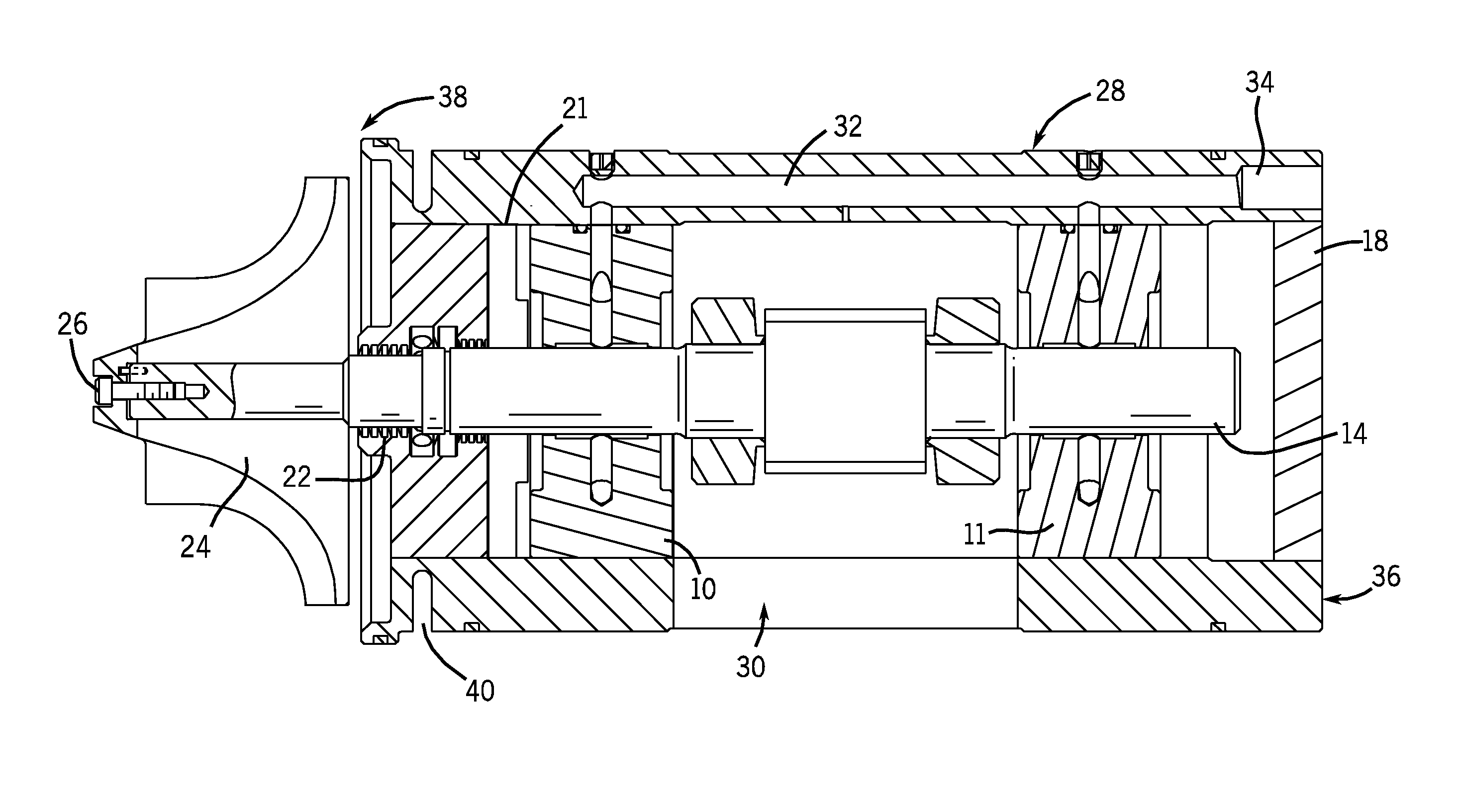
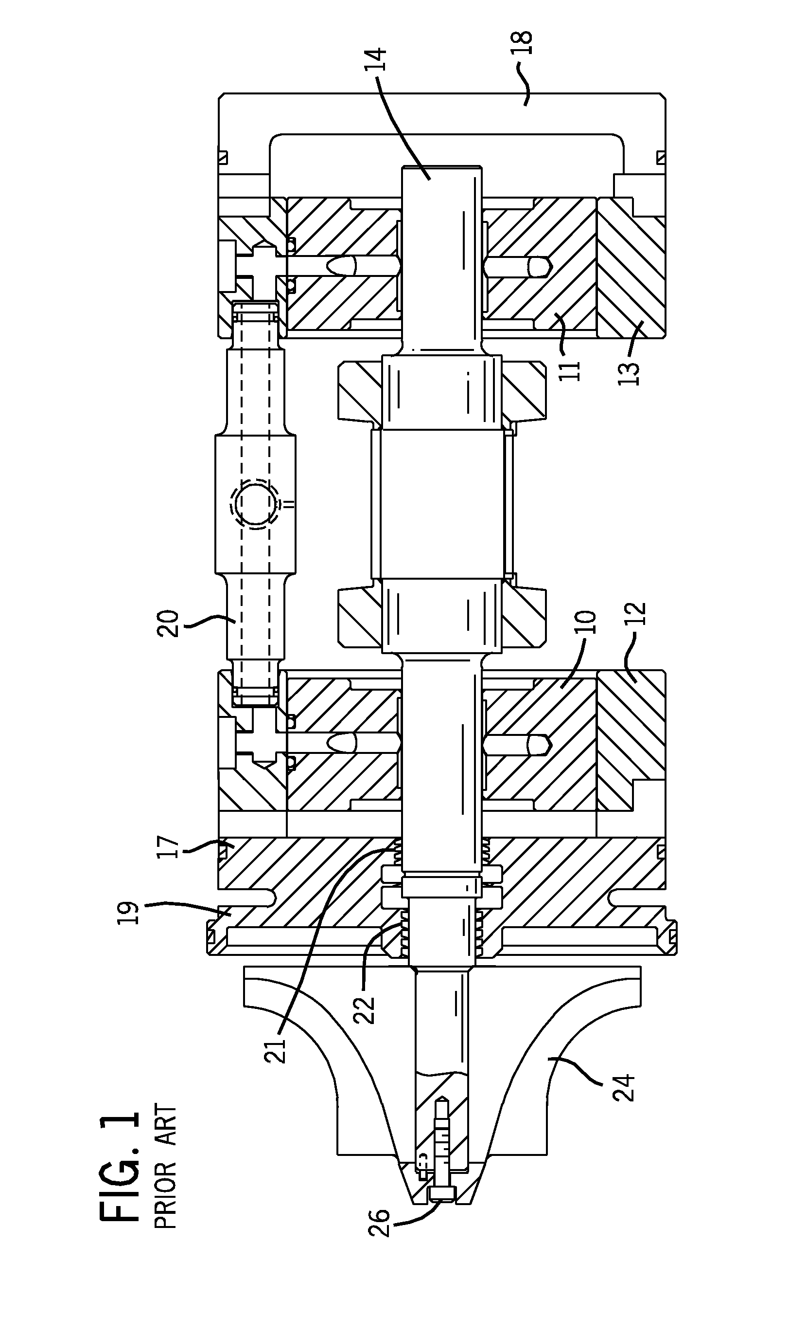
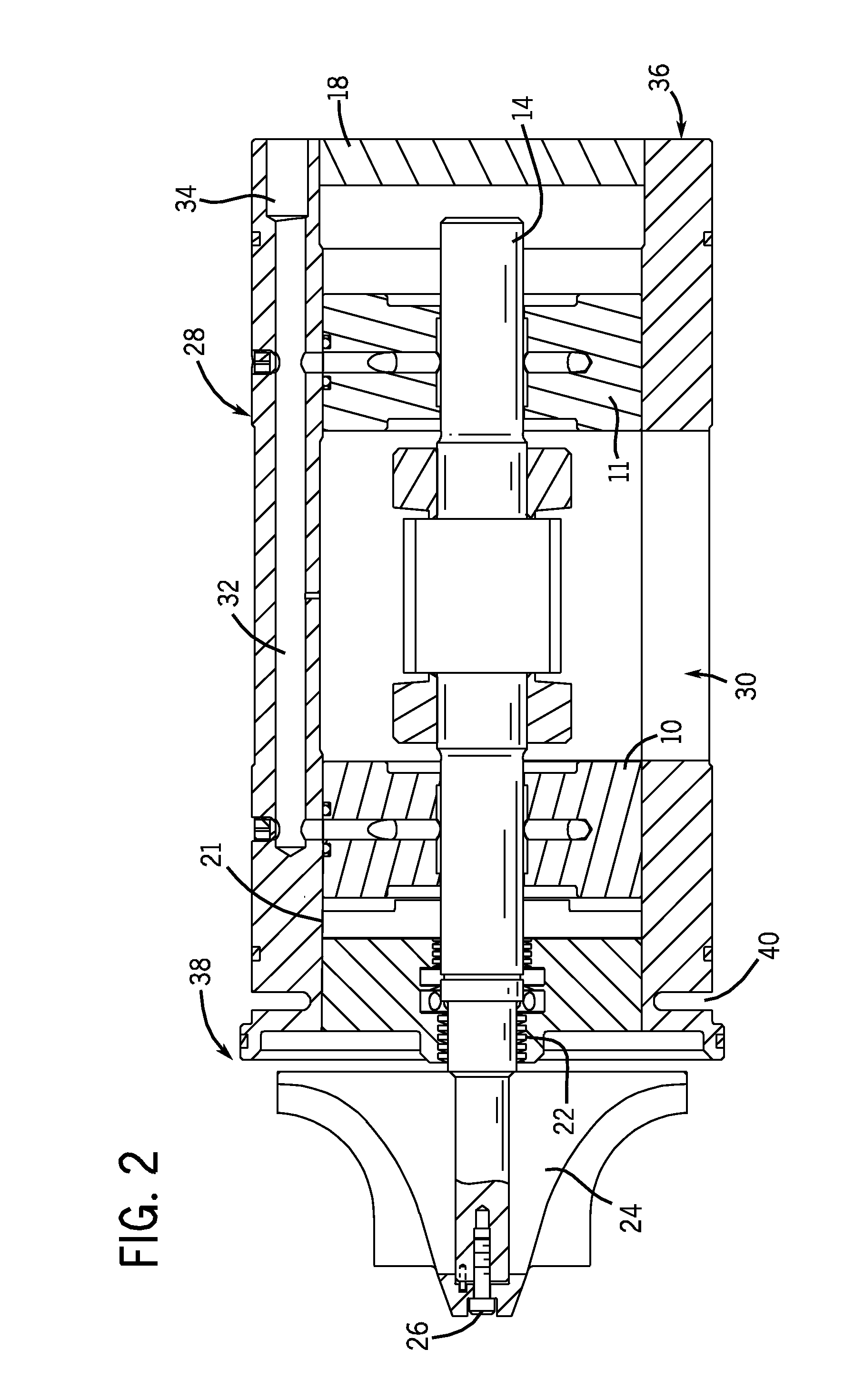
[0009]FIG. 1 represents the known way to assemble the illustrated components. Inner bearings 10 and 11 and outer housings 12 and 13 are mounted on a gearbox or compressor housing. Generally, the gearbox housing is horizontally split and the mating halves have a semicircular cutout so that upon assembly, the bearings are respectively supported in the opposed gearbox housing walls. A geared pinion shaft 14 extends through bearings 10 and 11. An end cap 18 goes over the end of the shaft 14. Various piping manifolds 20, which are connected to each of the bearings 10 and 11, are illustrated. An oil seal 21 and a gas seal 22 are mounted to respective housings 17 and 19. The gearbox housing can be integrally cast in halves to form the gearbox lower and upper housings so that the assembly is completed around the housings 12 and 13 and housings 17 and 19. An impeller 24 is fitted to the end of the pinion shaft 14 and secured with a bolt 26, preferably through the open end of the scroll or ge...


PUM

PropertyMeasurementUnit
outer diameteraaaaaaaaaa
diameteraaaaaaaaaa
driven speedaaaaaaaaaa

Abstract

Portions of the drive system for a piece of rotating equipment are pre-assembled into a subassembly. The subassembly can be held together by a carrier that is fabricated to accept the components in a proper alignment so that the carrier can be installed as a unit. In the preferred embodiment the carrier becomes a gearbox housing component that is installed saving the need for individual component alignment. Using the modular approach. The modular approach allows an assembly having a single part number to apply to a given compressor unit and further allows standardization of air ends of compressors with specific impellers and inlets added to meet requirements of a specific application.

Description

CROSS REFERENCE TO RELATED APPLICATION[0001]This application is a continuation of U.S. patent application Ser. No. 10 / 889,146, entitled “MODULAR ROTOR ASSEMBLY”, filed Jul. 12, 2004, which is herein incorporated by reference in its entirety.FIELD OF THE INVENTION[0002]The field of this invention is modular pre-assembly of rotating components of industrial machinery and more specifically compressors.BACKGROUND OF THE INVENTION[0003]Typically, when an end user specifies a compression need from a manufacturer the manufacturer tries to provide a unit from an available product line to meet the performance and price parameters given. Since the potential applications and the specific parameters given by different users can vary, each unit may be specifically built for a unique application. For example, in a drive system, the final driven speed for a unit can vary. Generally, various components of the drive system to be installed in a gearbox have to be individually assembled and aligned wi...

Claims


Application Information

Patent Timeline
Patent Type & Authority Applications(United States)
IPC IPC(8): F16C33/74B23P15/14F16C33/10
CPCF04B53/22F04D25/163Y10T29/49464F04D25/02F04D29/0563F04D29/624
Inventor CZECHOWSKI, EDWARD S.SMALL, ROBERTBATTERSHELL, JOHN R.KOLODZIEJ, ROBERT M.
Owner INGERSOLL RAND CO
Why Eureka
Try Eureka