
Stator Blade for a Turbomachine which is Exposable to Axial Throughflow, and also Stator Blade Arrangement for It

a turbomachine and stator blade technology, which is applied in the direction of liquid fuel engines, vessel construction, marine propulsion, etc., can solve the problems of comparatively large tolerances, comparatively low fitting accuracy in relation to the contour of the circumferential groove, and insensitive stator blade arrangement to thermal influences, so as to facilitate the insertion of stator blades

Inactive Publication Date: 2011-03-03
SIEMENS AG
View PDF13 Cites 19 Cited by
  • Summary
  • Abstract
  • Description
  • Claims
  • Application Information

AI Technical Summary

Benefits of technology

[0008]As a result of the stator blade arrangement according to the invention, a fixed clamping in the radial direction of the stator blade in the carrier structure of a turbomachine which is exposable to axial throughflow can be achieved. Since the tensioning force is first created when screwing in and tightening up the tensioning screw, the stator blade, and particularly its blade root, can be produced with comparatively large tolerances and with comparatively low fitting accuracy in relation to the contour of the circumferential groove. On the one hand, this facilitates the positioning, i.e. inserting and displacing the stator blade in the circumferential groove. On the other hand, the gaps which are required for thermal expansion can be provided in sufficient size as a result, which makes the stator blade arrangement insensitive to thermal influences.
[0019]According to another advantageous development, the carrier structure is formed as a stator blade carrier or as a turbomachine casing which can be split in half along its axial extent. This facilitates the insertion of stator blades in the circumferential groove. Also, the provision of a stator blade lock is avoided which otherwise in the case of a one-piece carrier structure would be necessary with a circumferential groove which would then be endless.

Problems solved by technology

Since the tensioning force is first created when screwing in and tightening up the tensioning screw, the stator blade, and particularly its blade root, can be produced with comparatively large tolerances and with comparatively low fitting accuracy in relation to the contour of the circumferential groove.
On the other hand, the gaps which are required for thermal expansion can be provided in sufficient size as a result, which makes the stator blade arrangement insensitive to thermal influences.

Method used


Image

  • Stator Blade for a Turbomachine which is Exposable to Axial Throughflow, and also Stator Blade Arrangement for It
  • Stator Blade for a Turbomachine which is Exposable to Axial Throughflow, and also Stator Blade Arrangement for It

Examples


Embodiment Construction

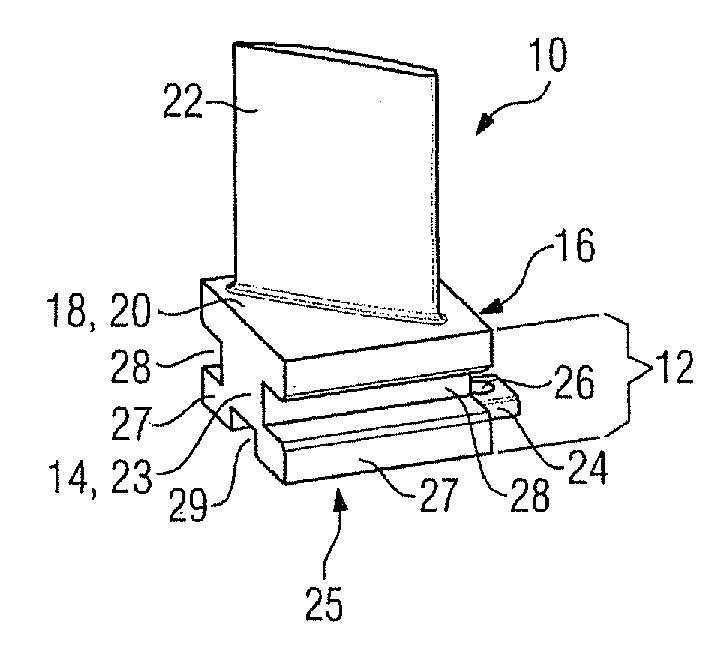
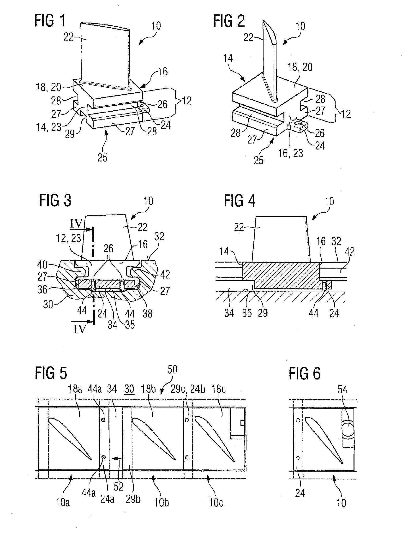
[0026]FIG. 1 and FIG. 2 show in perspective view, from different directions of view, a stator blade 10 according to the invention for a turbomachine. The stator blade 10 comprises a blade root 12 which has two oppositely disposed sides 14, 16. Between the two oppositely disposed sides 14, 16, a platform 18 is arranged, from the top surface 20 of which an aerodynamically curved blade airfoil 22, which extends transversely to it, projects in a free-standing manner.

[0027]On one (16) of the two sides 14, 16, a projecting shaped piece 24 is formed in the manner of a lug. The shaped piece 24 in this case is arranged in the middle close to an underside 25 of the blade root. In the shaped piece 24, there is a threaded hole 26, the thread axis of which is oriented perpendicularly to the plane of the top surface 20 of the platform 18.

[0028]On the other (14) of the two sides 14, 16, provision is made for a recess 29. The recess 29 of the stator blade 10 in question in this case is selected in ...


PUM


Abstract

A stator blade and a stator blade arrangement for a turbomachine which is exposable to axial throughflow is provided. Each stator blade is retained via a fixed clamping in a circumferential groove. For the fixed clamping, provision is made on one side of the blade root for a shaped piece with a threaded hole into which a tensioning screw, which is supported on the bottom of the circumferential groove, may be screwed.

Description

CROSS REFERENCE TO RELATED APPLICATIONS[0001]This application claims priority of European Patent Office application No. 09011070.1 EP filed Aug. 28, 2009, which is incorporated by reference herein in its entirety.FIELD OF INVENTION[0002]The invention refers to a stator blade for a turbomachine which is exposable to axial throughflow, comprising a blade root, having two sides disposed opposite each other, with a platform and at least one blade airfoil which is arranged thereupon. In addition, the invention refers to a stator blade arrangement with a carrier structure, on the inner generated surface of which provision is made for a circumferential groove in which stator blades, which are retained by means of a form fit, are seated in a butt-mounted manner.BACKGROUND OF INVENTION[0003]Such a stator blade and stator blade arrangement for a compressor are known for example from US 2005 / 0191177 A1. In the compressor casing, which is formed by two halves of an annulus, provision is made fo...

Claims


Application Information

Patent Timeline
Patent Type & Authority Applications(United States)
IPC IPC(8): B64C11/06
CPCF01D5/3038F01D5/32F04D29/644F04D29/542F01D9/042
Inventor KUSTERS, BERNHARDMITTELBACH, MARCSIEBER, UWEWALTKE, ULRICHWISTUBA, DIRK
Owner SIEMENS AG
Learn More