

Fuel cell composite flow field element and method of forming the same
a technology of flow field element and fuel cell, which is applied in the field of fuel cells, can solve the problems of heavy plate weight and cracking, affecting the overall cost of the fuel cell unit, and machining these plates from graphite, and achieves the effect of high thermal and electrical conductivity and easy manufacturing
- Summary
- Abstract
- Description
- Claims
- Application Information
AI Technical Summary
Benefits of technology
Problems solved by technology
Method used
Image

Examples
example 1
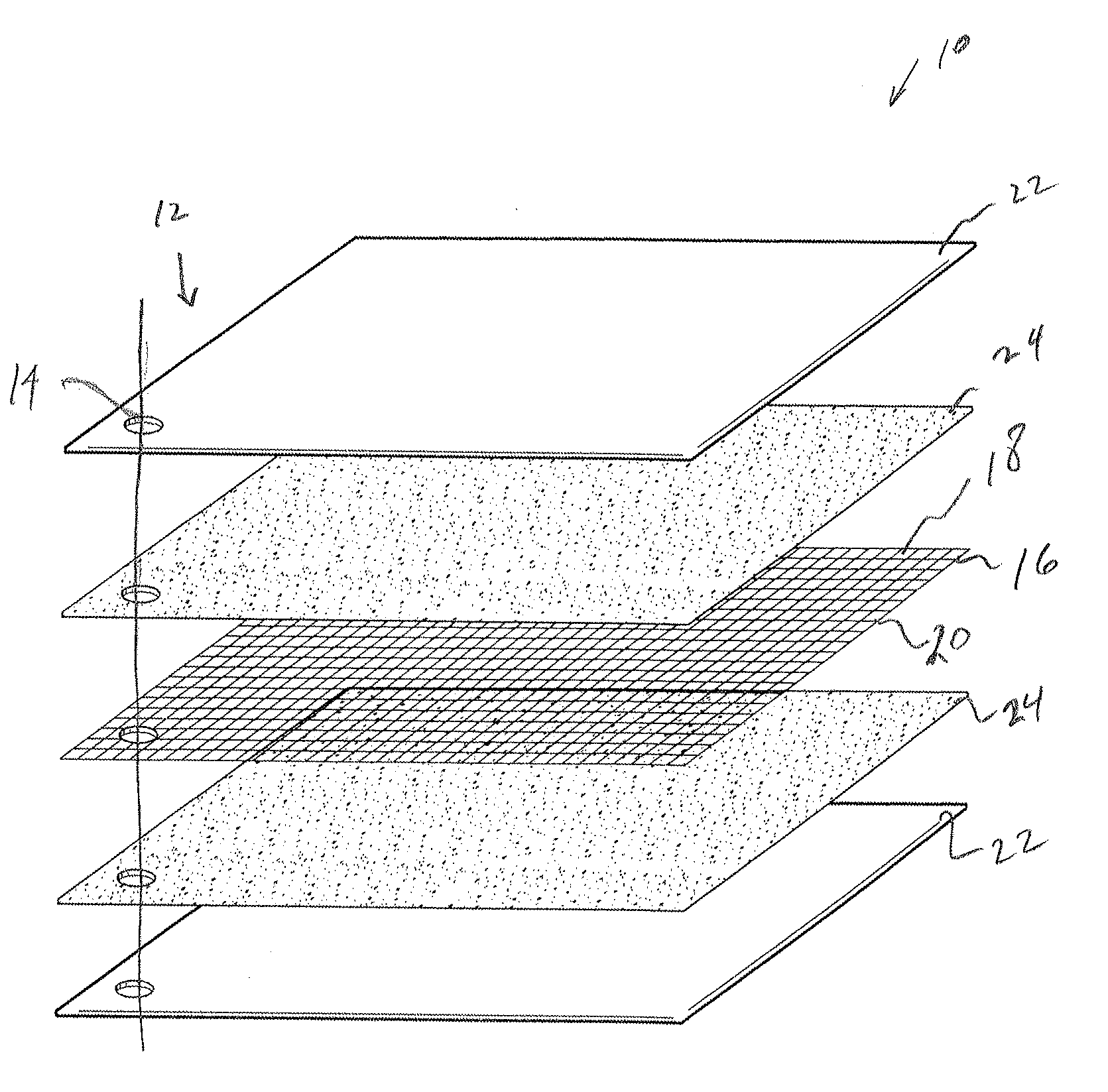
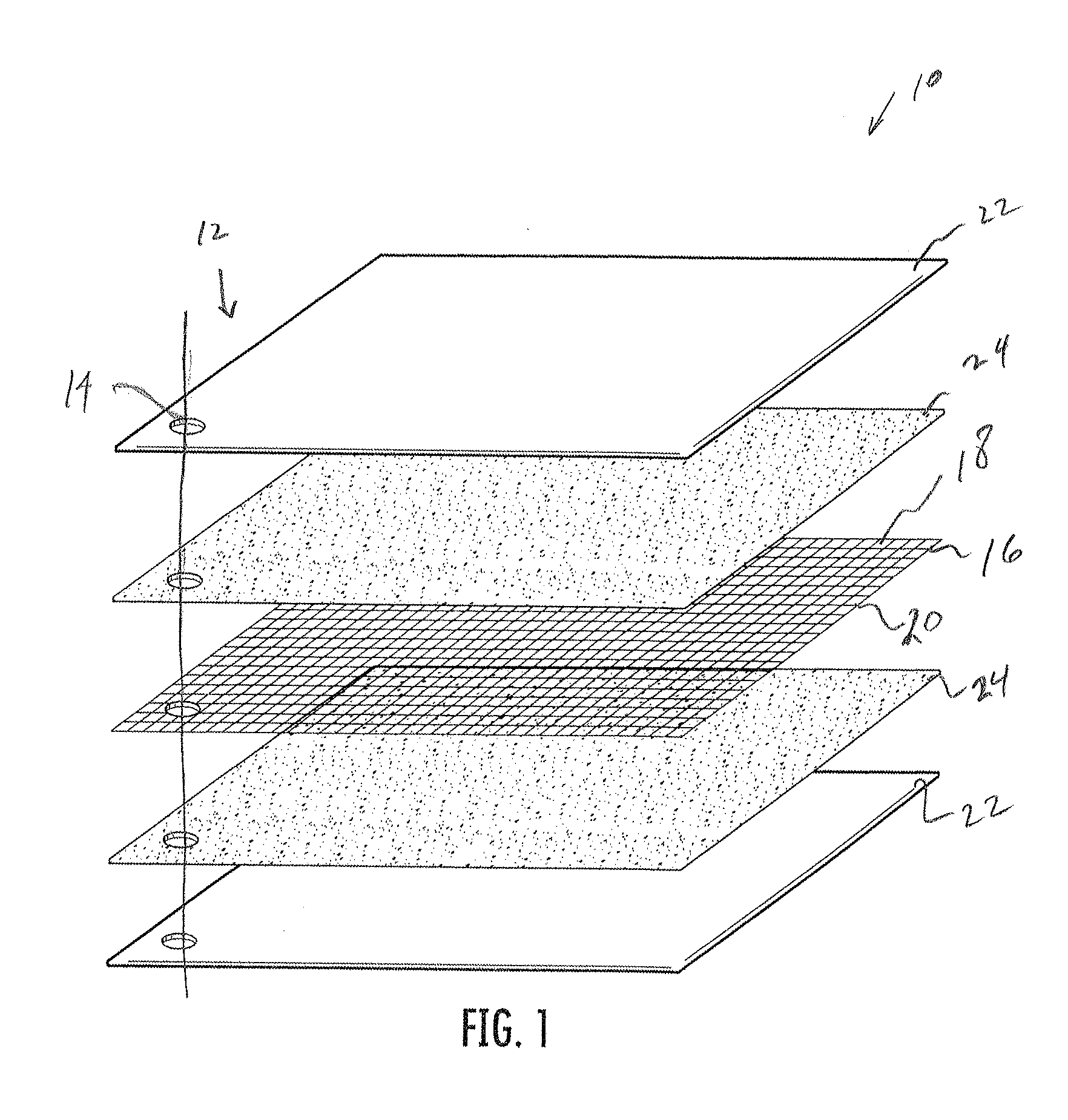
An electrically and thermally conductive composite can be formed from the following components:i). 316 stainless steel foil, 0.003 inches thickii). high temperature conductive adhesive, comprising:a). 10 mL part A, MG 832HT epoxy (MG Chemicals)b). 5 mL part B, MG 832HT epoxy (MG Chemicals)c). 6 grams Asbury #3243 graphite flake (Asbury Graphite)iii). GTA Grafoil flexible graphite, 0.005 inches thick (Graftech)
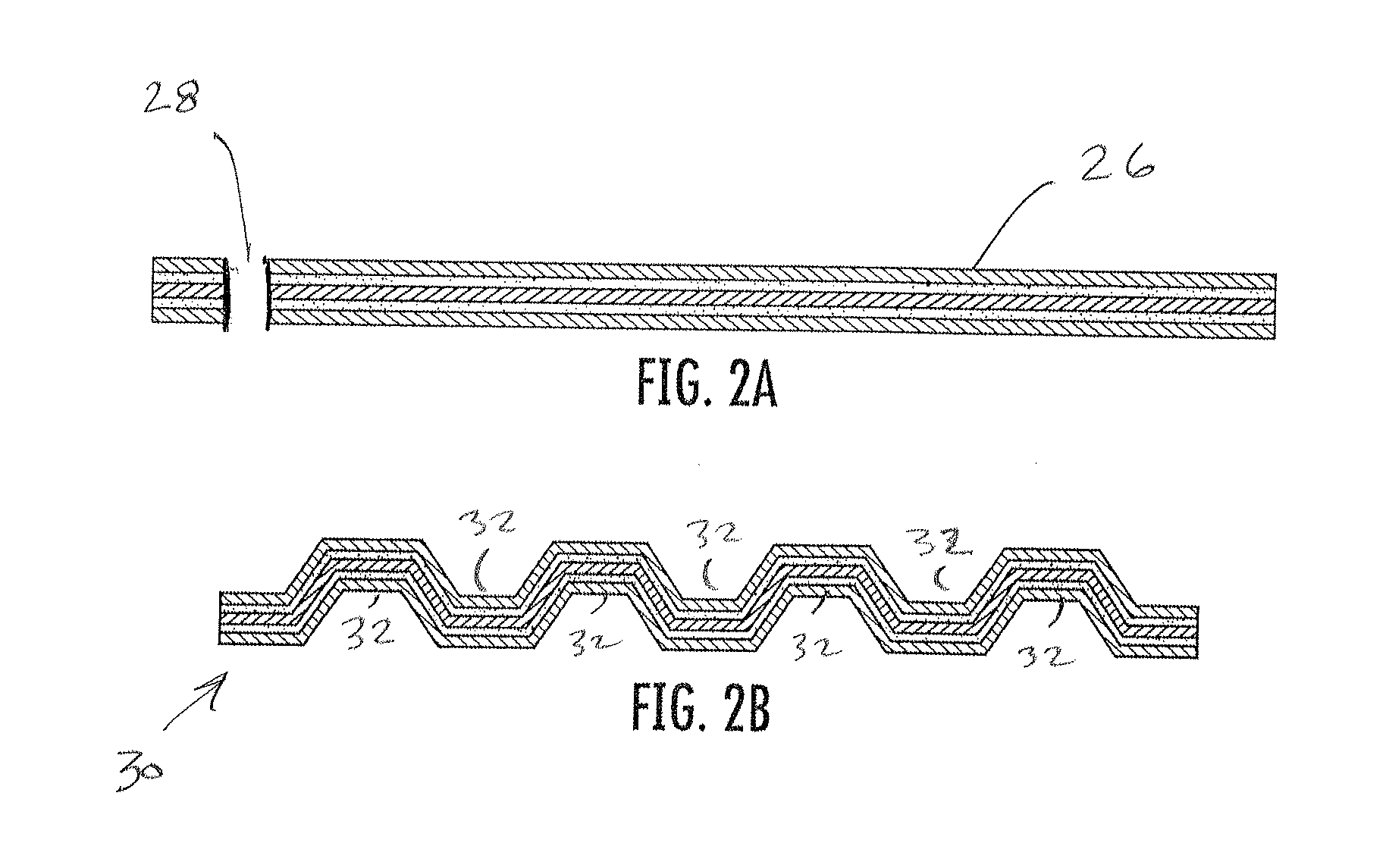
A composite comprising the above flexible graphite / conductive adhesive / stainless steel foil / conductive adhesive / flexible graphite is cured under pressure at 180 degrees F. for 1 hour. Passing the above composite through intermeshing splines forms a corrugated separator plate or flow field insert.
example 2
An electrically and thermally conductive composite can be formed from the following components:i). 316 stainless steel 100×100 mesh, 0.0045 inches diameter wire, 30.3% open areaii). high temperature conductive adhesive, comprising:a). 10 mL part A, MG 832HT epoxy (MG Chemicals)b). 5 mL part B, MG 832HT epoxy (MG Chemicals)c). 6 grams Asbury #3243 graphite flake (Asbury Graphite)iii). GTA Grafoil flexible graphite, 0.005 inches thick (Graftech)
A composite comprising the above flexible graphite / conductive adhesive / stainless steel mesh / conductive adhesive / flexible graphite is cured under pressure at 180 degrees F. for 1 hour. Passing the above composite through intermeshing splines forms a corrugated separator plate or flow field insert.
Table 4 shows a comparison of the electrical resistance properties between the composite of Example 1 (using metal foil) and the composite of Example 2 (using metal mesh). Comparison of Example 1 and 2 Through-plane Electrical Resistance
Clamping Pressur...
example 3
An electrically and thermally conductive composite can be formed from the following components:High Purity Graphite Flake—Asbury Graphite #3243PPS Polymer Powder—Chevron Phillips Ryton VIPropylene GlycolTriton X-100 surfactantStainless Steel Screen—McMaster Carr 9319T41, 0.0026″ wire dia., 37.8% openFlexible Graphite—Graphtec 0.005″ thick GTA Grafoil
The components are formed into a slurry mix in the following portions: PPS V-1 100 parts per weight (ppw); water, 260 ppw; propylene glycol, 20 ppw; wetting agent (Triton X-100), 4 ppw; graphite, 100 ppw. The components are placed in a ball mill with 5 / 32″ 302S.S. grinding media at 30 rpm for 12 hours.
To determine approximate amount of powder mixture needed for a given screen size, as an example, Powder mixture density (cured)=(1.35 g / cc+2.23 g / cc) / 2=1.79 g / cc, Overall mesh thickness=2*wire dia.=0.0052″=0.0132 cm, % open area of mesh=37.8%=0.378, Minimum mixture needed [g]=sample area(2.375×2×2.54̂2 cm2)*0.0132 cm*0.378*1.79 g / cc=0.2737 ...
PUM
| Property | Measurement | Unit |
|---|---|---|
| Time | aaaaa | aaaaa |
| Thickness | aaaaa | aaaaa |
| Thickness | aaaaa | aaaaa |
Abstract
Description
Claims
Application Information