Robotic Arm

Active Publication Date: 2011-03-03
OLIVER CRISPIN ROBOTICS
View PDF42 Cites 10 Cited by
  • Summary
  • Abstract
  • Description
  • Claims
  • Application Information

AI Technical Summary

Benefits of technology

[0013]At least one link in each segment may comprise a bearing member or surface for bearing against an adjacent surface. For example, some or all of the links may have wheels for running along the surface. This has th

Problems solved by technology

Others have hinge joints, which give a stiffer structure, but which are more limited in movement.
A problem with inspe

Method used


Image

  • Robotic Arm
  • Robotic Arm
  • Robotic Arm

Examples


Example

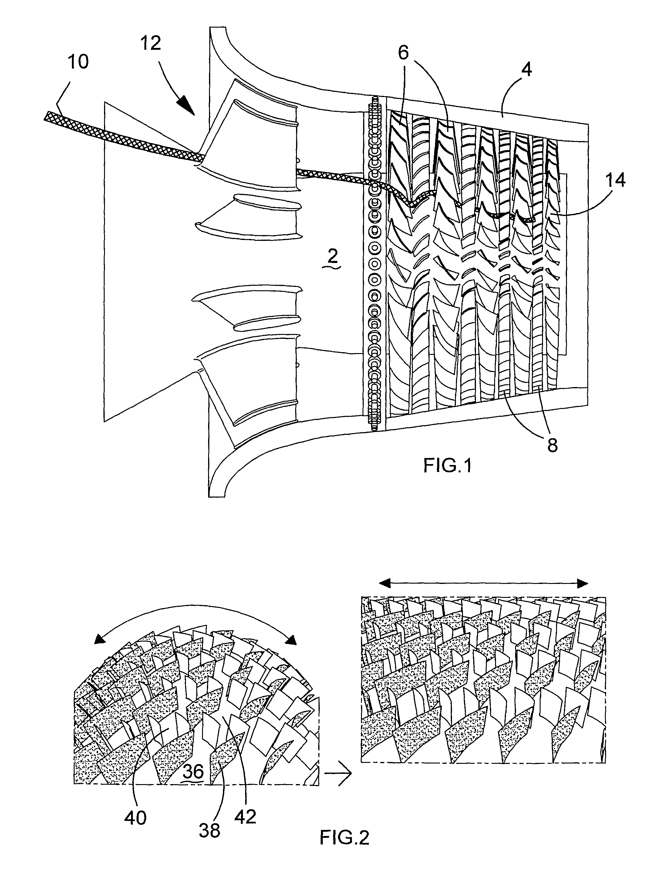
[0029]Referring to FIG. 1, a rotary machine comprising a gas turbine engine has a central rotor 2 and an outer casing 4. Several rows of rotor blades 6 are mounted on the rotor 2, and several rows of stator vanes 8 are mounted on the outer casing 4. Each row of stator vanes 8 is positioned between adjacent rows of rotor blades 6.

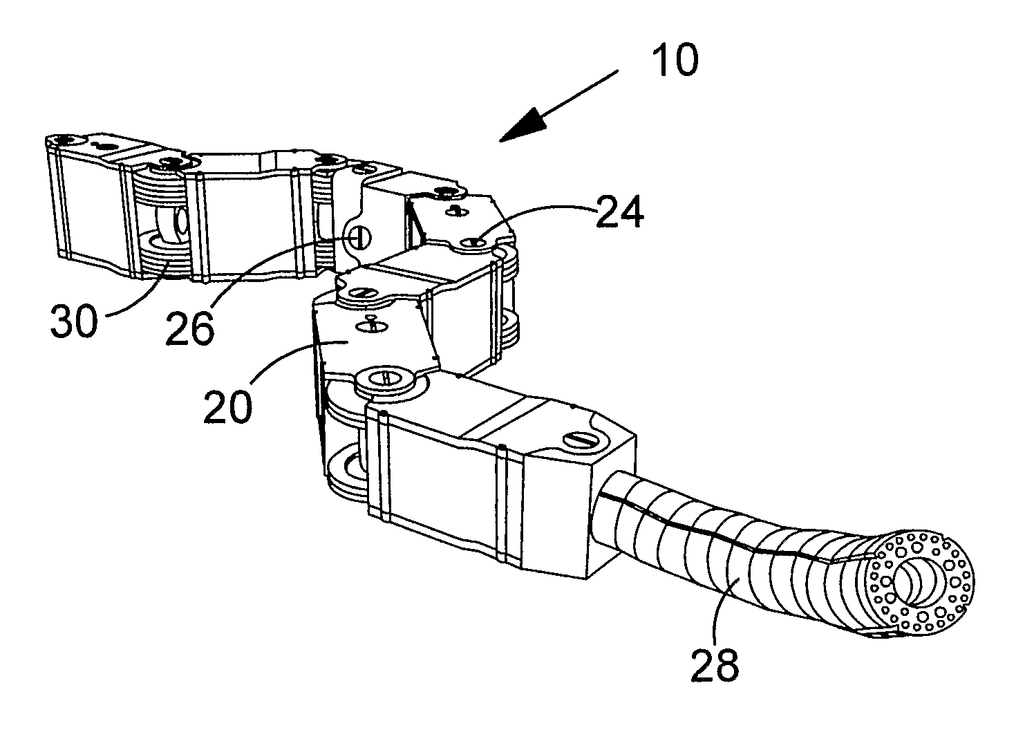
[0030]A robotic arm 10 is shown extending from the air intake 12 of the engine between the rotor blades and vanes of each row in order to reach a target blade 14.

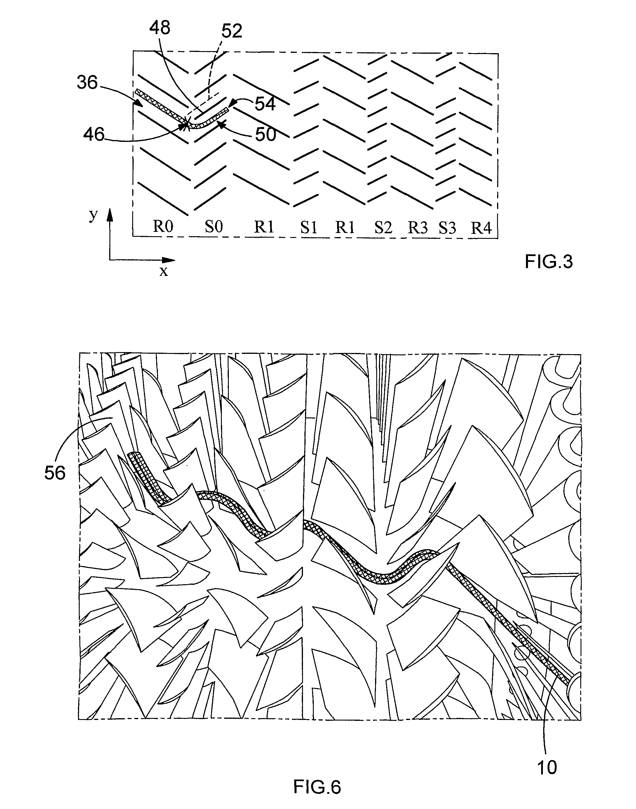
[0031]It will be appreciated that the relative positions of the rotor blades 6 with respect to the stator vanes 8 varies depending both on build configuration, and also on where the rotor comes to rest when the engine is switched off. Therefore it is not possible to determine, from outside the engine, the best path to take to reach the target blade 14. However it is generally known that the blades 6 or vanes 8 in each row are substantially identical, and are substantially evenly spaced. Therefore, i...


PUM


Abstract

A robotic arm is provided, for example for inspecting a rotary machine such as a gas turbine engine. The arm has a plurality of groups of links having articulations therebetween for movement in a first plane, the groups having articulations with respect to each other for movement in a second orthogonal plane. Thus the arm can move around objects such as aerofoils in the engine, and also move up or down to remain close to the rotary surface of the machine.

Description

CROSS-REFERENCE TO RELATED APPLICATIONS[0001]The present application is a continuation of pending International patent application PCT / GB2008 / 004259 filed on Dec. 22, 2008, which designates the United States and claims priority from British patent application number 0725095.4 filed on Dec. 21, 2007, the content of which is incorporated herein by reference.FIELD OF THE INVENTION[0002]This invention relates to a robotic arm, for example for use in a rotary machine, such as for inspecting and / or repairing blades of a gas turbine engine.BACKGROUND OF THE INVENTION[0003]Such arms comprise a plurality of articulated links. In some, all of the articulations are ‘universal’, or at least may bend in more than one plane, so that the arm can adopt various shapes. Others have hinge joints, which give a stiffer structure, but which are more limited in movement. Hinge joints can be used at alternating angles (eg perpendicular to each other) to improve flexibility of shape. These require separate ...

Claims


Application Information

Patent Timeline
IPC IPC(8): B25J9/06
CPCB08B9/045B25J9/06Y10T74/20329B25J9/104G02B23/2476B25J9/065
Inventor BUCKINGHAM, ROBERT OLIVERGRAHAM, ANDREW CRISPIN
Owner OLIVER CRISPIN ROBOTICS
Why Eureka
Try Eureka