
Metal alloy mono and poly-filament wire reinforced carbon fiber plating system with electromagnetic bone stimulation

a carbon fiber and electromagnetic bone stimulation technology, applied in the field of biomedical sciences, can solve the problems of obscuring the image of fractures and osteotomies, carbon fiber in the plating system has been developed in the past, and has not shown the stability and durability of its metallic counterparts, so as to improve improve the stability of the rigid foundation, and improve the effect of the mechanical strength of the carbon fiber structur

Active Publication Date: 2019-06-04
ELEMENTAL ORTHOPEDICS LLC
View PDF19 Cites 1 Cited by
  • Summary
  • Abstract
  • Description
  • Claims
  • Application Information

AI Technical Summary

Benefits of technology

This patent describes a method called inductive coupling which uses pulsed electromagnetic field (PEMF) stimulation to promote bone healing. This method involves using current-carrying coils placed on the skin over the fracture site to create an electrical field within the fracture site. The method is non-invasive, painless, and can be easily used at home. It can provide stability to the fracture site and promote faster recovery without the need for additional surgery. This patent provides a solution for patients who have a higher potential of forming a non-union of their fracture. The method provides a physiological environment that allows for quicker recovery and best opportunity to heal after fracture or surgery involving an osteotomy with plate or intramedullary nail fixation.

Problems solved by technology

These materials obscure the image of the fracture and osteotomy after their application due to their inherent property of radiopacity on X-ray evaluation.
Carbon fiber in plating systems has been developed in the past, but have not exhibited the stability and durability of their metallic counterparts.
One of the most common post-operative issues from fracture and osteotomy reduction is non-union of two boney fragment ends following surgical reduction.

Method used


Image

  • Metal alloy mono and poly-filament wire reinforced carbon fiber plating system with electromagnetic bone stimulation
  • Metal alloy mono and poly-filament wire reinforced carbon fiber plating system with electromagnetic bone stimulation
  • Metal alloy mono and poly-filament wire reinforced carbon fiber plating system with electromagnetic bone stimulation

Examples


example 1

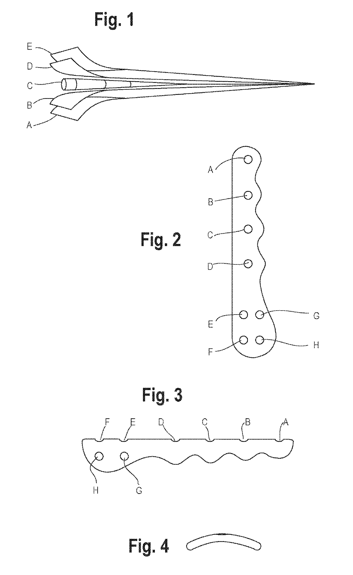
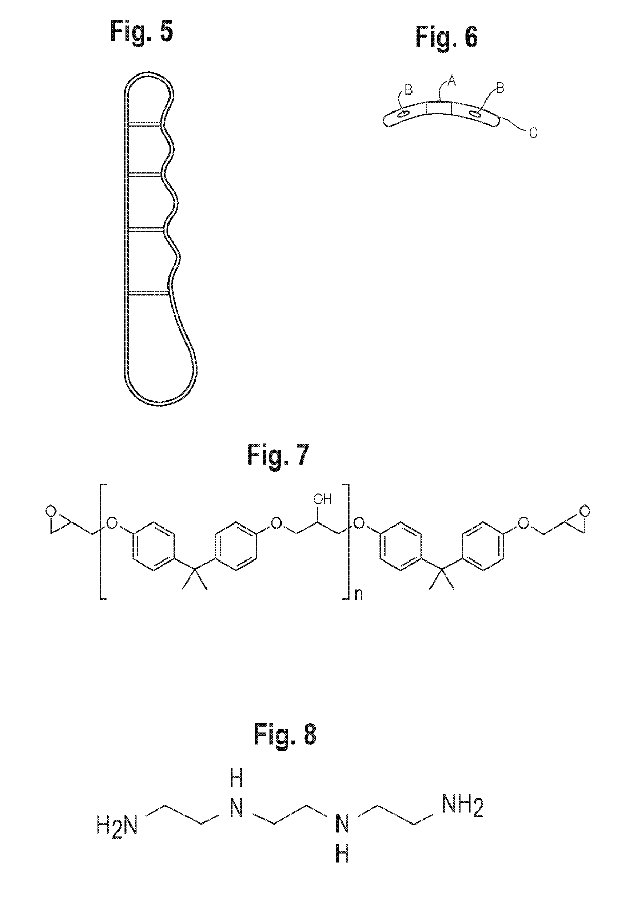
[0121]Fracture Fixation Plate Example, Fibula—is pre-contoured ⅓ tubular plate with a concentric superior surface to allow for maximal strength with minimal prominence to the adjacent tissues. The ⅓ tubular design is comprised of a curve transverse to the longitudinal axis has a constant radius along the longitudinal axis for at least a portion of the central trunk. The anterior surface remains without curvature and the posterior surface allows for curvature for limited contact and interface with the surrounding surfaces. The distal aspect of the plate is the anatomically contoured in a spoon shape to the distal portion of the osseous surface to allow for a larger surface area and acceptance of multiple fixation portals.

[0122]This combination of metal alloy wire to reinforce carbon fiber increases the resistance to bending, torsion, and tension deforming forces while maintaining the radiolucent properties of carbon fiber. This enables the physician to directly visualize the progress...


PUM

PropertyMeasurementUnit
currentsaaaaaaaaaa
currentsaaaaaaaaaa
currentsaaaaaaaaaa

Abstract

The invention entails metal alloy mono and poly-filament wire reinforced carbon fiber plating system for the fixation of skeletal fractures and osteotomies with electrical bone stimulation. For example, in some embodiments, systems and methods comprise a bone stimulation device by generating an electrical current from an implanted power pack, which travels through wire wrapped in the transverse / perpendicular plane around the mono-poly filament wires within the carbon fiber plate, creating an electromagnetic field. Such systems and methods find use in delayed or non-union events of bone and also in patients with acute bone fractures whom also suffer from other comorbidities predisposing the osteotomy or fracture to a non-union event.

Description

[0001]The present application claims priority to U.S. provisional patent application Ser. No. 62 / 186,482, filed on Jun. 30, 2015, the disclosure of which is herein incorporated by reference in its entirety.TECHNICAL FIELD[0002]Provided herein are systems, devices, and methods in the field of the biomedical sciences related to internal fixation of all types of orthopedic skeletal fractures.BACKGROUND[0003]Current options for internal fixation of skeletal fractures and osteotomies include metallic devices consisting of stainless steel and titanium. These materials obscure the image of the fracture and osteotomy after their application due to their inherent property of radiopacity on X-ray evaluation. Carbon fiber in plating systems has been developed in the past, but have not exhibited the stability and durability of their metallic counterparts.[0004]One of the most common post-operative issues from fracture and osteotomy reduction is non-union of two boney fragment ends following sur...

Claims


Application Information

Patent Timeline
Patent Type & Authority Patents(United States)
IPC IPC(8): A61B17/80A61F2/28A61N1/362A61N1/36A61B17/72A61L31/12A61N1/32A61B17/00H01M10/0525
CPCA61N1/36A61B17/72A61B17/80A61L31/122A61N1/326H01M2220/30A61B2017/00734A61F2002/2821A61L2430/02H01M10/0525A61B2017/00221Y02E60/10
Inventor TACKTILL, JORDAN
Owner ELEMENTAL ORTHOPEDICS LLC
Learn More