Stepping motor driving apparatus
a technology of stepping motors and driving apparatuses, which is applied in the direction of electrical apparatus, control systems, dynamo-electric converter control, etc., can solve the problems of increasing the loss of iron generated in the motor, the loss of copper in the motor may not be sufficiently decayed, and the loss of electric current may not be sufficiently large, so as to reduce noise or vibration and the loss of motors
- Summary
- Abstract
- Description
- Claims
- Application Information
AI Technical Summary
Benefits of technology
Problems solved by technology
Method used
Image
Examples
first embodiment
[0030][Stepping Motor Driving Apparatus]
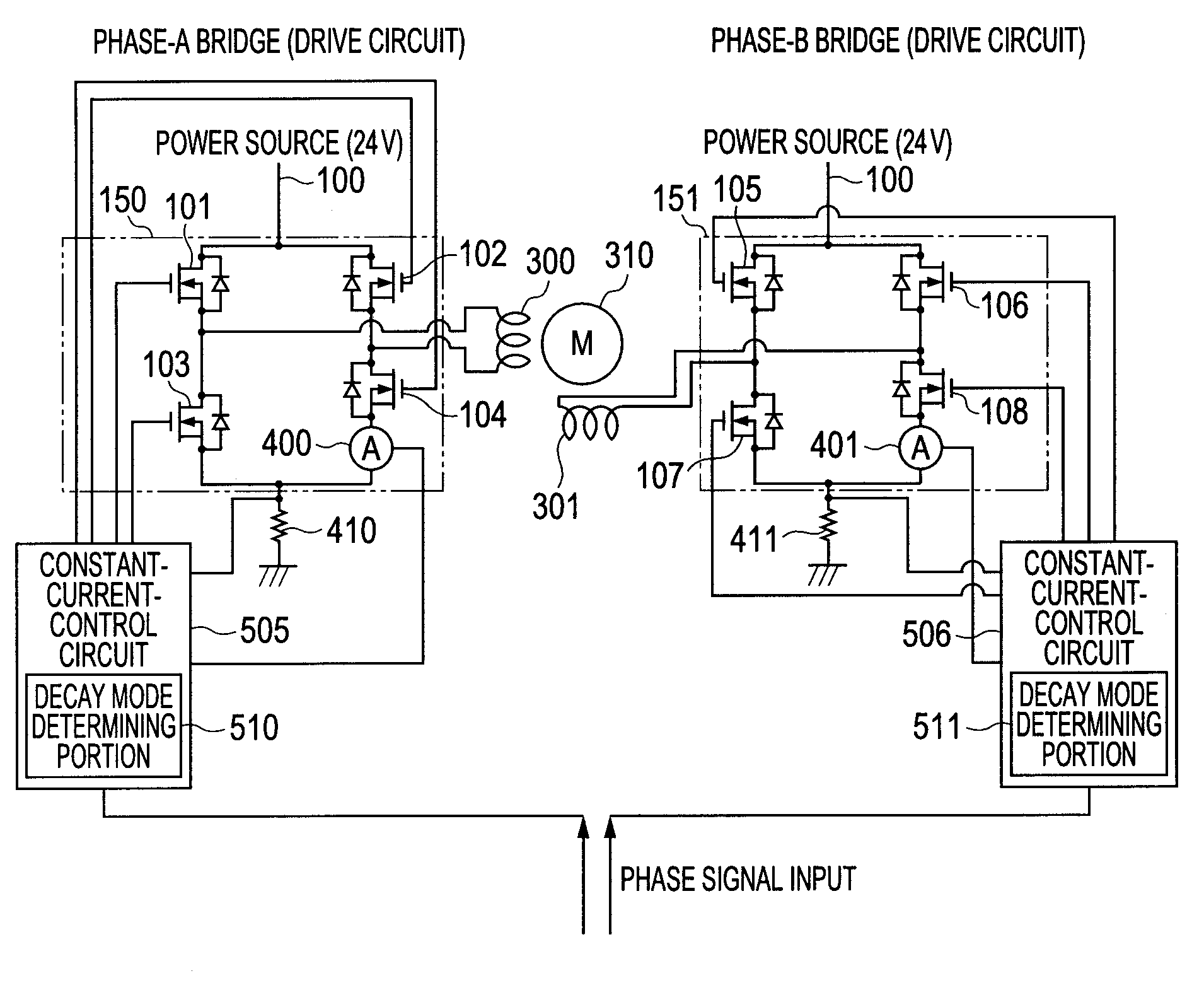
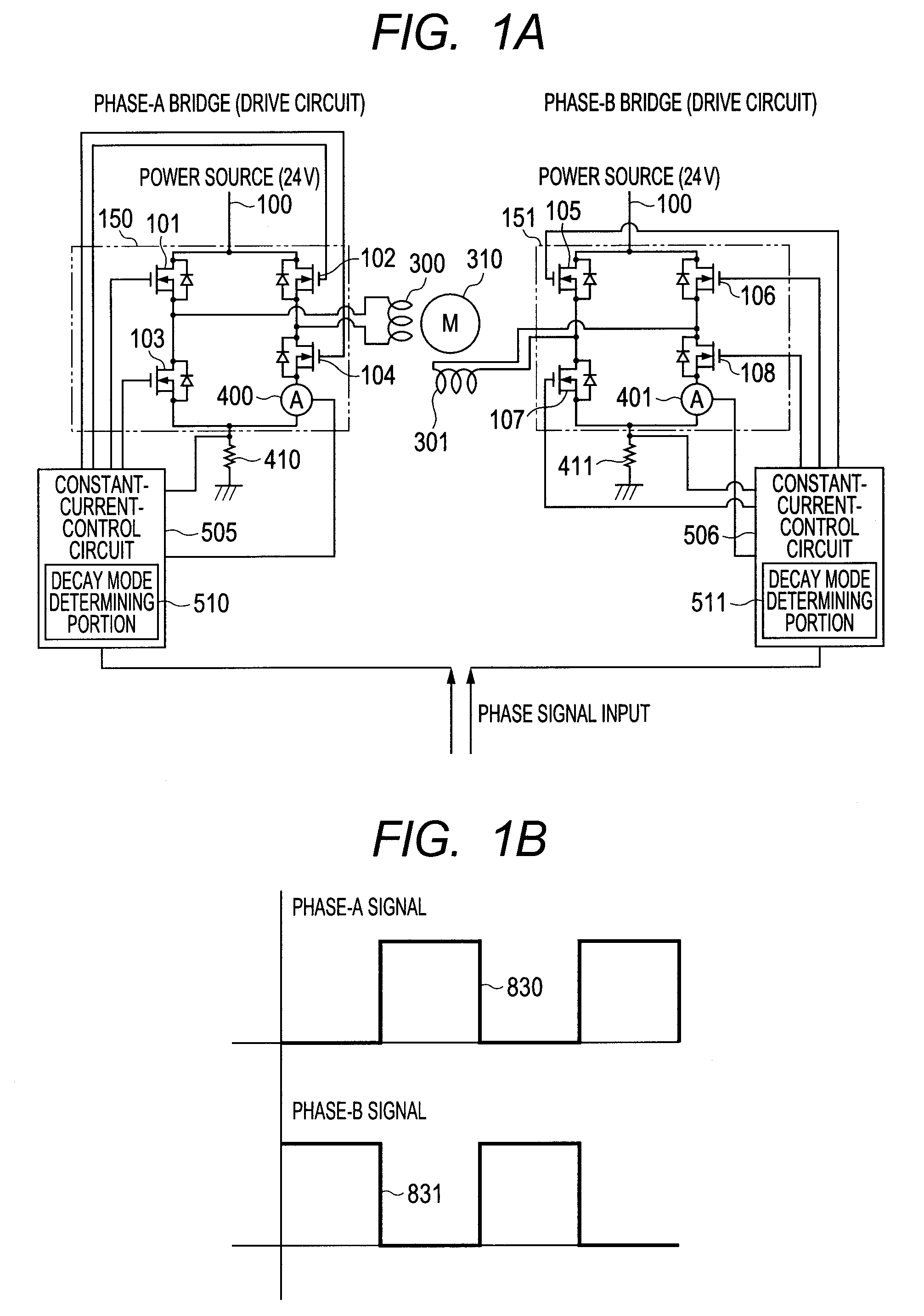
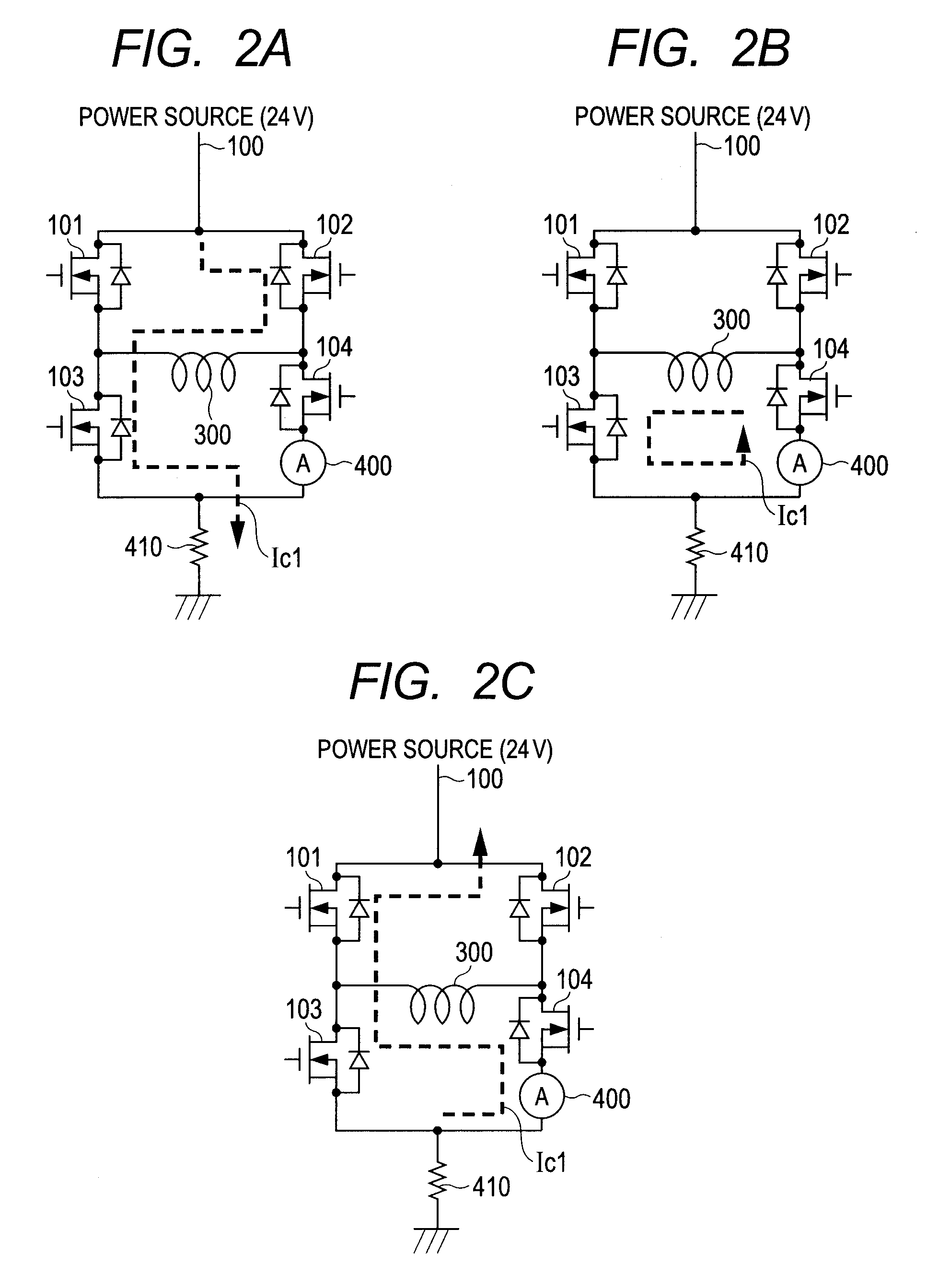
[0031]A stepping motor driving apparatus according to a first embodiment will be described. FIG. 1A is a diagram illustrating a configuration of the stepping motor driving apparatus according to this embodiment. In this embodiment, coils of the motor are subjected to a constant-current driving. A method of driving a stepping motor 310 will be described by taking two-phase excitation as an example. As illustrated in FIG. 1A, similarly to the related art, in this embodiment, a coil current is allowed to flow by one H bridge circuit per one phase of the coils of the stepping motor. A drive signal of the stepping motor 310 is input as a phase signal from an external controller (not shown). With the drive signal, constant-current control circuits 505 and 506 turn on / off switching elements (field-effect transistors (FETs)) 101 to 108 of the H bridge circuits, to thereby allow a predetermined electric current corresponding to the phase signal to pass...
second embodiment
[0051]A stepping motor driving apparatus according to a second embodiment will be described. The same structures as those in the first embodiment are denoted by identical symbols, and their description is omitted. This embodiment is different from the first embodiment in that, as illustrated in FIGS. 7A and 7B, the decay mode determining threshold It2 is set to be larger than the current set value (constant current setting value) It1, and the low decay rate period is selected immediately after the feed period.
[0052]In a waveform of FIG. 7A, when the current decay is executed in the low decay rate mode during the decay period immediately after the feed period, the coil current Ic1 is appropriately decayed. For comparison, when the decay mode determining threshold It2 is set to be smaller than the current set value It1, as illustrated in FIG. 6A, the current ripple is larger than that in this embodiment because the first current decay in the current decay period is conducted in the hi...
PUM
 Abstract
Description
Claims
Application Information
 - R&D
- Intellectual Property
- Life Sciences
- Materials
- Tech Scout
- Unparalleled Data Quality
- Higher Quality Content
- 60% Fewer Hallucinations
Browse by: Latest US Patents, China's latest patents, Technical Efficacy Thesaurus, Application Domain, Technology Topic, Popular Technical Reports.
© 2025 PatSnap. All rights reserved.Legal|Privacy policy|Modern Slavery Act Transparency Statement|Sitemap|About US| Contact US: help@patsnap.com


