High-frequency switch

a high-frequency switch and switch technology, applied in the field of high-frequency switches, can solve problems such as malfunction or breakdown of transceivers, communication cannot be made normally, and achieve the effects of reducing production costs, reducing size, and improving communication efficiency

Inactive Publication Date: 2011-03-10
SOSHIN ELECTRIC
View PDF10 Cites 9 Cited by
  • Summary
  • Abstract
  • Description
  • Claims
  • Application Information

AI Technical Summary

Benefits of technology

[0023]With the high frequency switch according to the present invention, as described above, at least a reflected wave of a transmission signal can be detected even with a single high frequency switch. Also, it is possible to enhance the reduction in the number of parts used for a transmission system or a transceiving system with a reflected wave detection function, the reduction in size, the reduction in a production cost, and the reduction in a transmission loss.

Problems solved by technology

Then, the communication cannot be made normally, which may also lead to malfunction or breakdown of the transceiver 100.

Method used


Image

  • High-frequency switch
  • High-frequency switch
  • High-frequency switch

Examples


Embodiment Construction

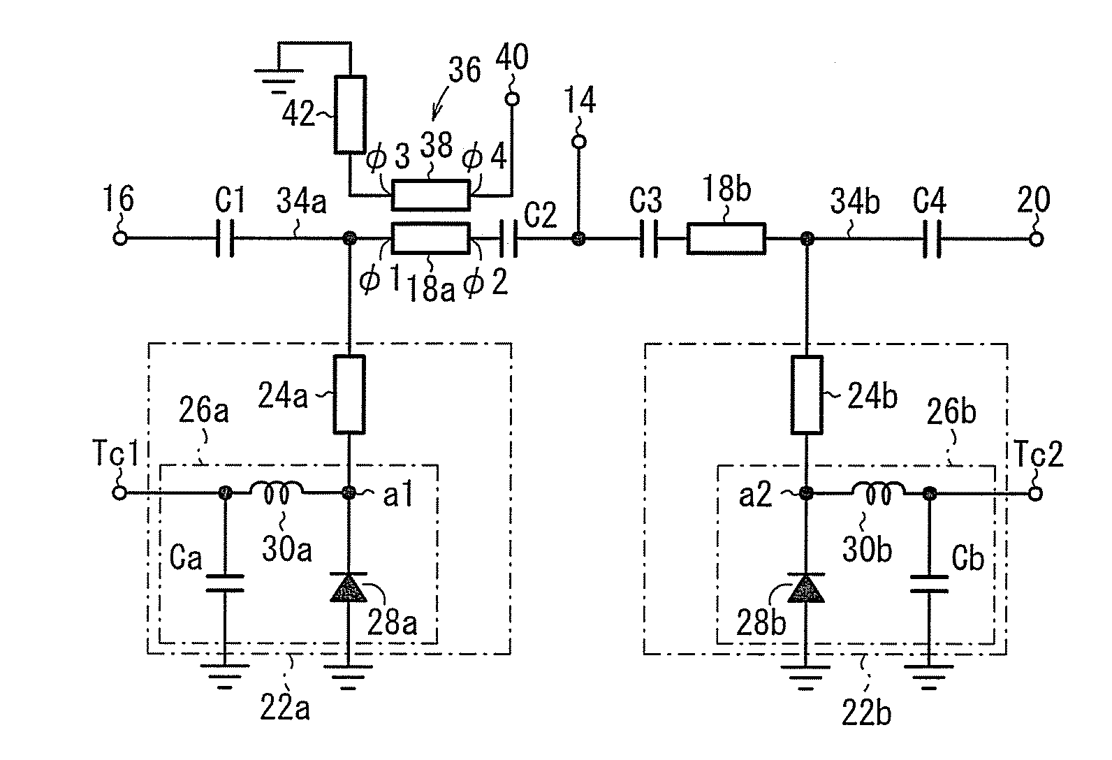
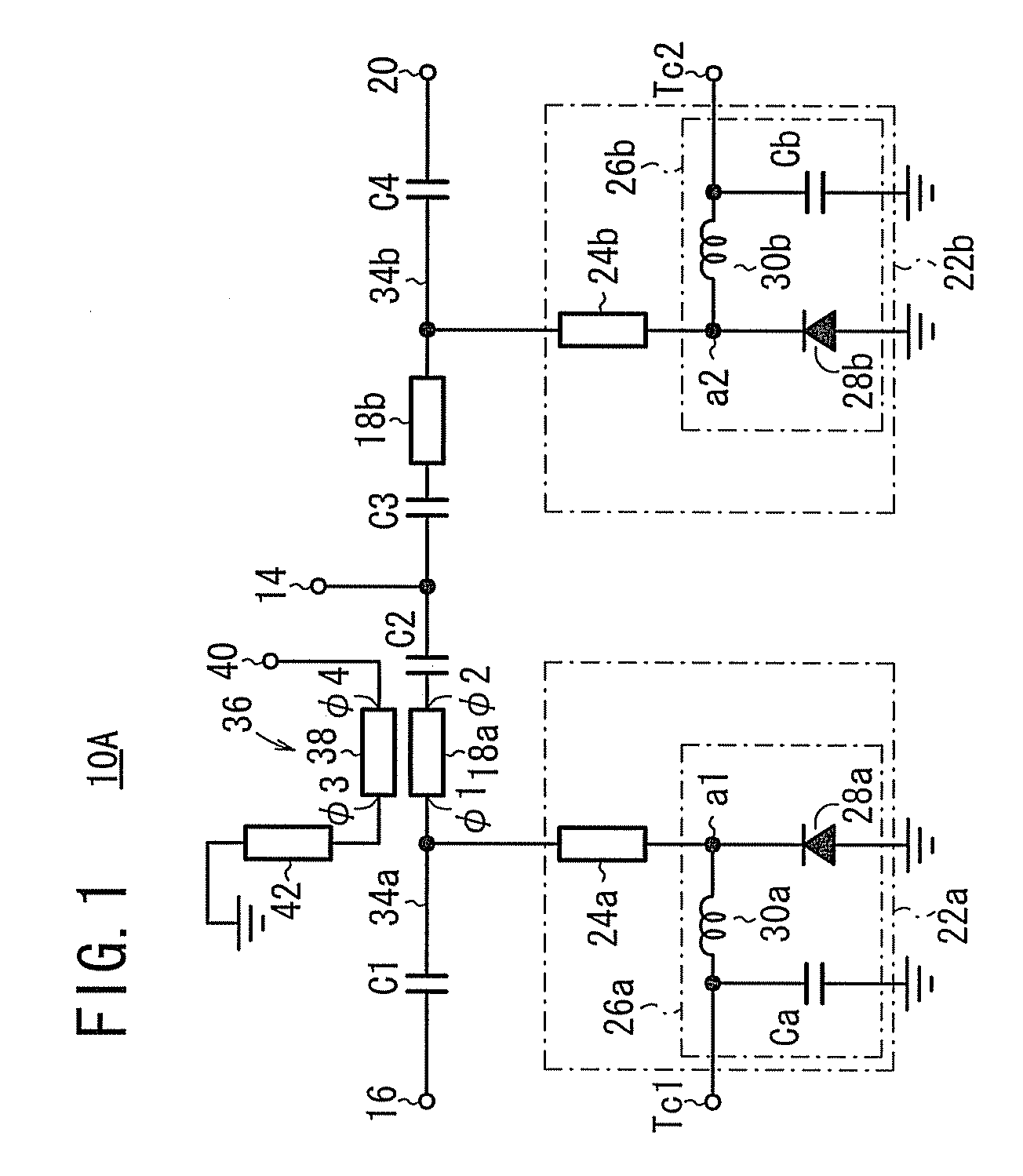
[0042]Embodiments wherein a high frequency switch according to the present invention is applied, for example, to an antenna switch will be described below with reference to FIGS. 1 through 16. It is assumed that λ represents a wavelength corresponding to the central frequency of an operating frequency band of the switch, and refers to a wavelength in transmission lines described below.

[0043]As shown in FIG. 1, an antenna switch according to a first embodiment (hereinafter referred to as a first antenna switch 10A) comprises a first λ / 4 signal transmission line 18a connected between an antenna connection terminal 14 and a transmission terminal 16, a second λ / 4 signal transmission line 18b connected between the antenna connection terminal 14 and a reception terminal 20, a first switch circuit 22a connected parallel to the first λ / 4 signal transmission line 18a, and a second switch circuit 22b connected parallel to the second λ / 4 signal transmission line 18b. Capacitors C1 through C4 a...


PUM


Abstract

Provided is a high-frequency switch formed by a first switch circuit connected in parallel to a first λ/4 signal transmission path for transmitting a transmission signal from a transmission terminal and a second switch circuit connected in parallel to a second λ/4 signal transmission path for transmitting a reception signal to a reception terminal. The high-frequency switch further includes a directivity coupler which has the first λ/4 signal transmission path as a constituent element and detects a reflected wave of the transmission signal. The directivity coupler includes: the first λ/4 signal transmission path; a λ/4 signal line arranged to oppose to the first λ/4 signal transmission path; a reflected wave output terminal connected to one end of the λ/4 signal line; and a terminal resistor connected to the other end of the λ/4 signal line.

Description

TECHNICAL FIELD[0001]The present invention relates to a high frequency switch for switching between high frequency signals, and more particularly to a high frequency switch suitable for use as an antenna switch connected to an antenna, e.g., a TDD (Time Division Duplex) switch or the like.BACKGROUND ART[0002]Conventional high frequency switches such as antenna switches include a microwave switch disclosed in Japanese Patent No. 2532122 and a transmission and reception switching device disclosed in Japanese Patent No. 2830319, for example.[0003]The microwave switch disclosed in Japanese Patent No. 2532122 has PIN diodes inserted in series and parallel in a signal line. Forward currents are passed through the PIN diodes to turn them on, and the PIN diodes are reversely biased to turn them off, thereby switching between high frequency signals.[0004]The transmission and reception switching device disclosed in Japanese Patent No. 2830319 employs a circuit scheme wherein a switch is const...

Claims


Application Information

Patent Timeline
Patent Type & Authority Applications(United States)
IPC IPC(8): H01P1/15H01P5/18
CPCH01P1/2135H01P1/15
Inventor ANDO, AKIRA
Owner SOSHIN ELECTRIC
Why Eureka
Try Eureka