Wi-Fi/BPL Dual Mode Repeaters for Power Line Networks

a power line network and repeater technology, applied in the field of data transmission, can solve the problems of power line communication system limitation to relatively low data rates, high lease fee, and limited network ownership of third-party providers, and achieve the effect of maintaining network connectivity over power lines

Active Publication Date: 2011-03-10
AMERICAN TELEPHONE & TELEGRAPH CO
View PDF24 Cites 15 Cited by
  • Summary
  • Abstract
  • Description
  • Claims
  • Application Information

AI Technical Summary

Benefits of technology

[0007]The present inventors have essentially solved the above problem. Specifically, the present inventors have invented a method and apparatus for maintaining network connectivity over power lines, even if various customers are covered by different power line networks or if one or more power lines in a network are unavailable to transmit data. More particularly, in order to bridge a gap in a power line network, one or more messages are extracted from a first node in a power line network and are then transmitted to a second node via free space transmission, illustratively wireless radio frequency (RF) transmission conforming to one or more of the 802.11a, b or g standards. When those messages are received at the second node, the message is injected back into the power line on the other side of a gap in power line coverage. Thus, when an interruption occurs, for example due to a fallen power line or maintenance to a line, network data is transmitted from one wireless access point to another, thus allowing for continued network coverage.

Problems solved by technology

However, if a third-party provider wishes to establish a new service or compete with the more traditional service providers, that third-party must typically pay a fee to lease the distribution network of the traditional service provider.
This lease fee is typically high and, as a result, it is frequently the case that a third-party provider cannot offer as competitive a price for its products as can the network-owning traditional service providers.
Initially, such power line communication systems were limited to relatively low data rates, typically less than 500 kbps.
While existing power line systems are capable of transmitting data at the rates described above, they were not initially designed for data transmission.
Additionally, unlike many data transmission networks, power line networks were only designed with limited, if any, redundancy for the paths from one point to another.
Therefore, in many instances, it would be difficult to provide power line data network service to customers on different power networks.
Additionally, if a power line failed or was unavailable for any reason (e.g., for maintenance), network destinations served by that power line would lose network connectivity.

Method used


Image

  • Wi-Fi/BPL Dual Mode Repeaters for Power Line Networks
  • Wi-Fi/BPL Dual Mode Repeaters for Power Line Networks
  • Wi-Fi/BPL Dual Mode Repeaters for Power Line Networks

Examples


Embodiment Construction

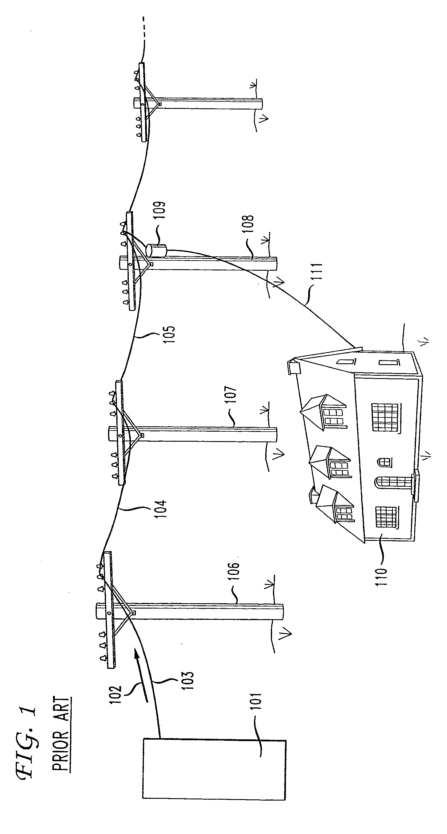
[0012]FIG. 1 shows a portion of a power network such as that commonly used to deliver electricity to homes and businesses. In that figure, substation 101 receives electricity from one or more power plants via transmission equipment and high voltage transmission lines. As is well known, transformers in substation 101 step down the power from transmission level voltages (extremely high voltages) to distribution voltages (typically less than 35,000 volts). Buses at the substation then split the distribution power off in multiple directions, such as direction 102 in FIG. 1. Electricity conducting wires, such as illustrative wires 103, 104 and 105, are suspended above the ground by poles, such as poles 106, 107 and 108. The electricity is stepped down once again to an illustrative 120 / 240 Volts by transformer 109 and is then delivered to an end destination, such has house 110, via tap wire 111. One skilled in the art will recognize that, while an overhead power line system is shown in FI...


PUM


Abstract

A method and apparatus for maintaining network connectivity over power lines is disclosed. Such network connectivity is maintained even if various customers are covered by different power line networks or if one or more power lines in a network are unavailable to transmit data. More particularly, in order to bridge a gap in a power line network, one or more messages are extracted from a first node in a power line network and are then transmitted to a second node via free space transmission, illustratively wireless radio frequency (RF) transmission conforming to one or more of the 802.11a, b or g standards. When those messages are received at the second node, the message is injected back into the power line on the other side of a gap in power line coverage. This method of transmission backup will continue until power line connectivity is restore upon which the preferred method will be selected and used.

Description

[0001]This application claims the benefit of U.S. Provisional Application No. 60 / 532,773, filed Dec. 24, 2003, which is hereby incorporated herein by reference.BACKGROUND OF THE INVENTION[0002]This application relates generally to data transmission and, more particularly, to data transmission over power lines.[0003]Telecommunications and other network service providers require physical access to end destinations, such as homes and businesses, in order to deliver their services. Various methods of delivering services to an end destination are typically available. For example, local phone companies have extensive networks of network delivery equipment directly to homes and businesses for delivering telephony and networking services (e.g., Internet access). Additionally, cable television providers have a similarly extensive network for delivering television content, network access and other services to homes and businesses.[0004]Therefore, traditional service providers have a readily a...

Claims


Application Information

Patent Timeline
Patent Type & Authority Applications(United States)
IPC IPC(8): H04L25/00
CPCH04B1/74H04B2203/5441H04B17/309H04L43/0823H04B3/54H04B3/46H04B3/58H04L43/0811H04L43/0847
Inventor AU, ALAN K.BARZEGAR, FARHADDOLAN, EDWARD J.GERSZBERG, IRWINOKORA, JEREMIAH A.
Owner AMERICAN TELEPHONE & TELEGRAPH CO
Why Eureka
Try Eureka