Rotary anode x-ray tube

a technology of x-ray tube and anode, which is applied in the direction of x-ray tube, electrical discharge tube, electrical apparatus, etc., can solve the problems of reducing the load carrying capacity of the bearing, affecting the performance of the bearing, and affecting the surface of the targ

Active Publication Date: 2011-03-10
CANON ELECTRON TUBES & DEVICES CO LTD
View PDF5 Cites 9 Cited by
  • Summary
  • Abstract
  • Description
  • Claims
  • Application Information

AI Technical Summary

Problems solved by technology

If the temperature of the electron colliding surface exceeds its allowable temperature, the surface of the target starts to be damaged.
However, as the size of the target increases, the size of the X-ray tube increases, leading to higher weight and manufacturing cost of the X-ray tube.
As a result, if the temperature of the rotary cylinder becomes high, a load carrying capacity of the bearing is lowered and a normal rotational motion is disabled.
However, if the wall thickness of the stationary shaft is decreased, sufficient anti-G performance is not obtained due to lowered rigidity of the stationary shaft.
That is, in the conventional X-ray tube, it is difficult to simultaneously realize the improvement of the anti-G performance and the high output.
For this reason, an area where viscosity friction of the liquid metal is generated increases, leading to increased frictional loss.
Accordingly, the increase in the size and the weight of the X-ray tube apparatus becomes a problem.
That is, it is further difficult to simultaneously realize the improvement of the anti-G performance and the high output.
Accordingly, cooling performance may not be constant and reliability of the cooling performance is low.
As described above, in the conventional X-ray tube, it is difficult to simultaneously realize the improvement of the anti-G performance and the high output.

Method used


Image

  • Rotary anode x-ray tube
  • Rotary anode x-ray tube
  • Rotary anode x-ray tube

Examples


first embodiment

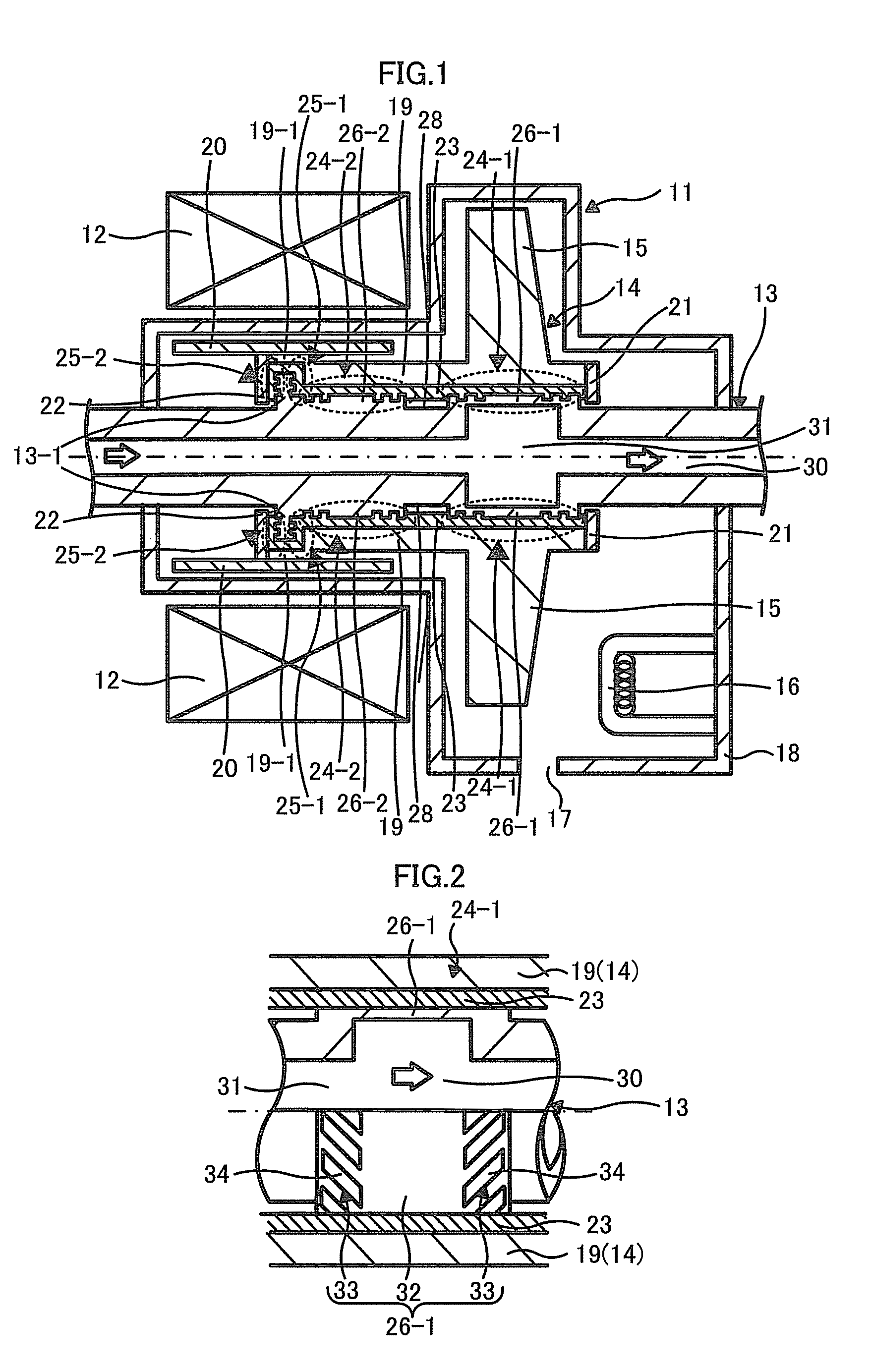
FIG. 1 is a cross-sectional view illustrating a rotary anode X-ray tube apparatus including a rotary anode X-ray tube 11 according to a first embodiment along a stationary shaft 13 to be described below, which illustrates when a rotary anode 14 to be described below rotates. The rotary anode X-ray tube apparatus (hereinafter, simply referred to as X-ray tube apparatus) illustrated in FIG. 1 includes a rotary anode X-ray tube 11 (hereinafter, simply referred to as X-ray tube 11) that radiates X-rays, a stator coil 12, and a casing (not illustrated) that stores the X-ray tube 11 and the stator coil 12.

The X-ray tube 11 includes a stationary shaft 13, a rotary anode 14 that is rotatably provided in the stationary shaft 13, a cathode 16 that is disposed to face a target 15 included in the rotary anode 14, and a vacuum enclosure 18 that stores these components and has a transmissive window 17 provided in a portion thereof. The X-ray tube 11 has a so-called both-end supported structure wh...

second embodiment

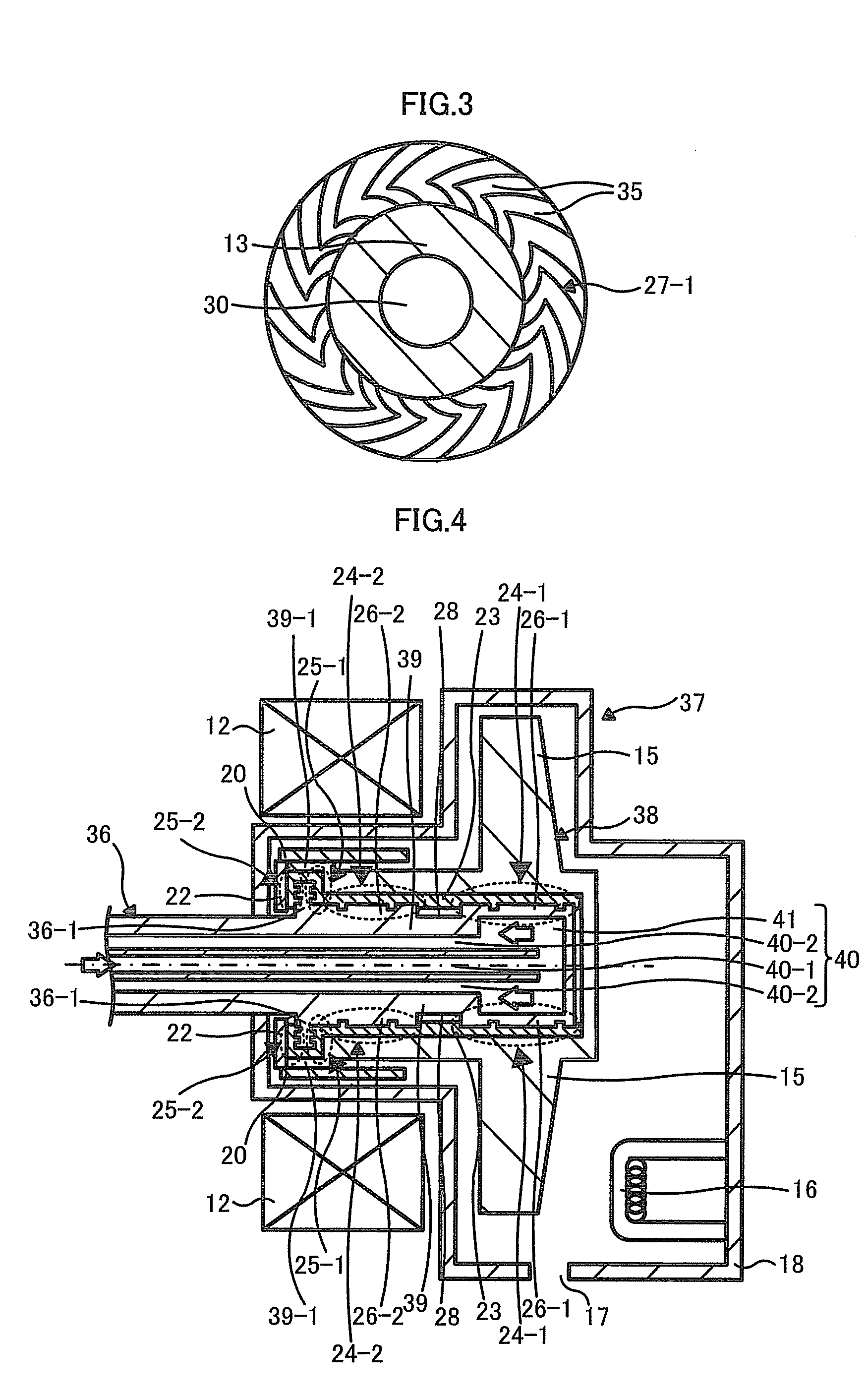
FIG. 4 is a cross-sectional view illustrating a rotary anode X-ray tube apparatus including a rotary anode X-ray tube 37 according to a second embodiment along a stationary shaft 36, which illustrates when a rotary anode 38 rotates. In the description of the X-ray tube apparatus, only portions that are different from those of the X-ray tube apparatus illustrated in FIG. 1 will be described.

The X-ray tube apparatus illustrated in FIG. 4 is different from the X-ray tube apparatus illustrated in FIG. 1 in that the X-ray tube apparatus illustrated in FIG. 4 has an X-ray tube 37 with a so-called cantilevered structure where the stationary shaft 36 is supported to one side of the vacuum enclosure 18. That is, in the X-ray tube 37 according to the second embodiment, one end of the stationary shaft 36 is positioned in the vacuum enclosure 18.

In the X-ray tube 37 according to the second embodiment, the stationary shaft 36 has a cylindrical shape having a bottom that is provided with a flow p...

third embodiment

FIG. 5 is a cross-sectional view illustrating a rotary anode X-ray tube 49 according to a third embodiment along a stationary shaft 45, which illustrates when the rotary anode 14 rotates. As illustrated in FIG. 5, the X-ray tube 49 according to the third embodiment is the same as the X-ray 11 according to the first embodiment in that a flow passage 47 provided in the stationary shaft 45 has a cooling bath 48, but is different from the X-ray tube 11 according to the first embodiment in that the cooling bath 48 is provided by thinning the wall thickness of the first large-diameter portion 26-1, the second large-diameter portion 26-2, and the stationary shaft 45 between the first and second large-diameter portions 26-1 and 26-2 to uniformly. That is, the third embodiment is different from the first embodiment in that the length of the cooling bath 48 in the axial direction of the stationary shaft 45 is increased.

The supporting mechanism of the rotary anode 14 is the same as that of the...


PUM


Abstract

A rotary anode X-ray tube apparatus according to an embodiment of the present invention includes a stationary shaft, a cooling bath that is provided in the stationary shaft, a rotary cylinder that is rotatably supported to the stationary shaft, a target that is provided in the rotary cylinder, a cathode that is disposed to face the target, and a vacuum enclosure that stores these components. The stationary shaft has a large-diameter portion provided in a portion thereof and is provided with a flow passage through which a cooling fluid flows. The cooling bath is provided by thinning the wall thickness of the large-diameter portion to increase the flow passage diameter of a portion of the flow passage. The rotary cylinder covers an area of the stationary shaft including the large-diameter portion through a liquid metal and is rotatably supported to the stationary shaft. The target has a hollow circular plate shape that is provided on an outer circumferential surface of the rotary cylinder. The vacuum enclosure stores the stationary shaft, the rotary cylinder, the target, and the cathode and supports the stationary shaft.

Description

CROSS REFERENCE TO RELATED APPLICATIONSThis application is based upon and claims the benefit of priority from the prior Japanese Patent Application No. 2009-207424 filed in Japan on Sep. 8, 2009; the entire contents of which are incorporated herein by reference.FIELDEmbodiments described herein relate generally to a rotary anode X-ray tube that is provided with a hydrodynamic bearing rotatably supporting a target.BACKGROUNDRotary anode X-ray tube apparatuses are used in medical and industrial diagnosis systems that are represented by computed tomography (CT) apparatuses. In general, a rotary anode X-ray tube apparatus includes a rotary anode X-ray tube that radiates X-rays, a stator coil, and a casing that stores the rotary anode X-ray tube and the stator coil.A conventional rotary anode X-ray tube includes a stationary shaft that has a flange portion provided in a portion thereof, a rotary anode that is rotatably provided in the stationary shaft, a cathode that is disposed to face ...

Claims


Application Information

Patent Timeline
Patent Type & Authority Applications(United States)
IPC IPC(8): H01J35/00
CPCH01J35/101H01J2235/1086H01J2235/106H01J35/104
Inventor TADOKORO, CHIHARUITO, YASUTAKAHATTORI, HITOSHITAKAHASHI, RYOICHIYONEZAWA, TETSUYANAKAMUTA, HIRONORI
Owner CANON ELECTRON TUBES & DEVICES CO LTD
Why Eureka
Try Eureka