Active liquid metal thermal spreader

a liquid metal thermal spreader and active technology, applied in the field of semiconductor devices, can solve the problems of increasing heat, increasing the reliance on conventional air-cooled methods, and reaching the limits of current forced air cooling methods,

Inactive Publication Date: 2006-07-20
IBM CORP
View PDF1 Cites 51 Cited by
  • Summary
  • Abstract
  • Description
  • Claims
  • Application Information

AI Technical Summary

Problems solved by technology

However, it is generally concluded that current methods of forced air cooling have reached their limits of performance.
As such, the trend towards smaller, more powerful chips that generate even greater amounts of heat makes continued reliance on conventional air-cooled methods inadequate.

Method used


Image

  • Active liquid metal thermal spreader
  • Active liquid metal thermal spreader
  • Active liquid metal thermal spreader

Examples


Embodiment Construction

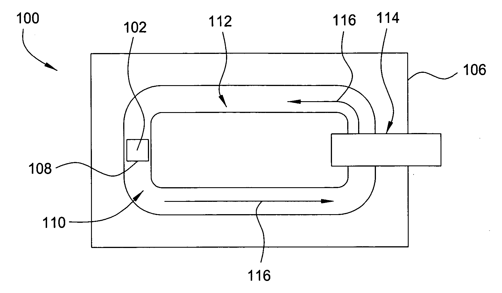
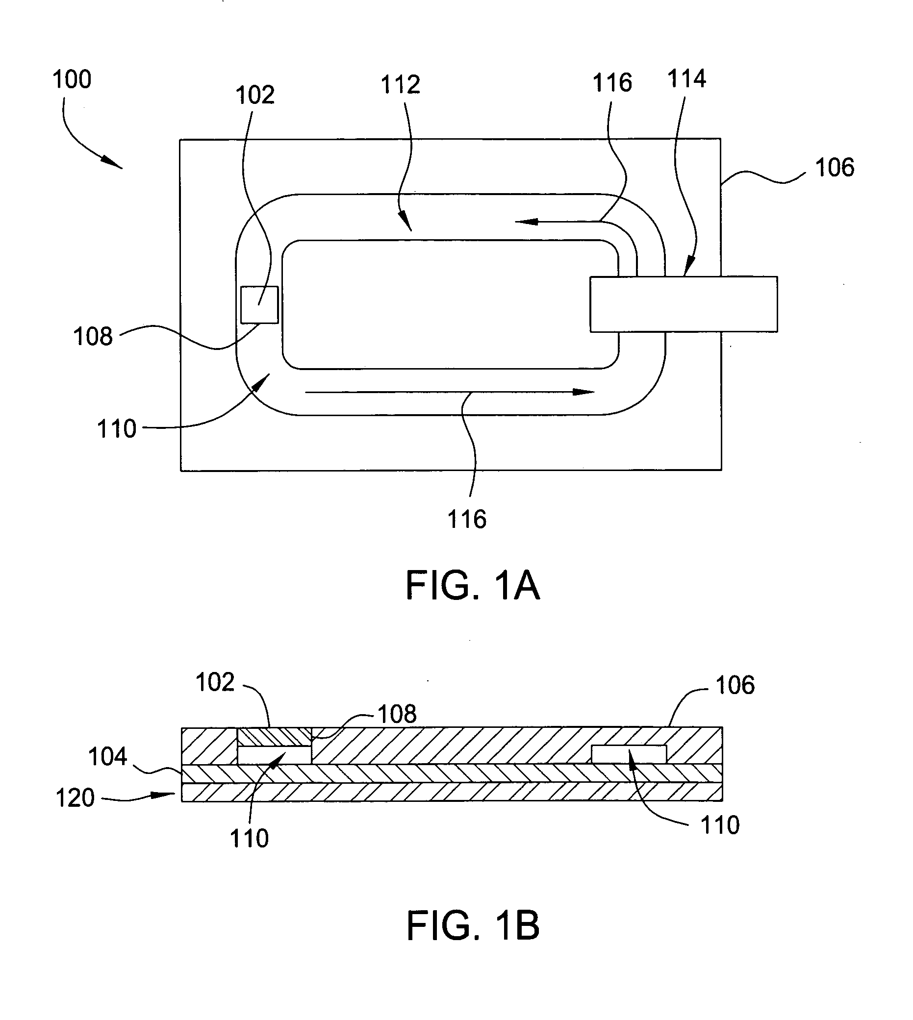
[0016]FIGS. 1A and 1B respectively depict top and side views of one embodiment of a thermal spreader 100. The thermal spreader 100 includes a substrate 106 coupled to a heat sink 104 and having a fluid flow channel 110 defined therebetween for circulating a coolant 112. The substrate 106 may comprise a thermally conductive or non-conductive material, such as metal, plastic or ceramic. In one embodiment, the substrate 106 is plastic or ceramic.

[0017] The heat sink 104 is a thermally conductive material, such as a metal, disposed beneath the substrate 106. The heat sink 104 and the substrate 106 may be coupled together by adhesive or by mechanical joining, such as by screwing, bolting, clamping, and the like, in a manner suitable to prevent leakage of the coolant 112 from the channel 110. Optionally, a gasket (not shown) may be interposed between the substrate 106 and the heat sink 104. In one embodiment, the heat sink 104 comprises copper or aluminum.

[0018] Optionally, a coating (n...


PUM


Abstract

The present invention is a method and apparatus for cooling a semiconductor heat source. In one embodiment a thermal spreader is provided and includes a substrate for supporting the semiconductor heat source and a heat sink coupled to the substrate. A channel is disposed between the heat sink and substrate. The channel has at least one wall defined by the heat sink. The surface area of the channel wall defined by the heat sink is about 10 to about 100 times the surface area of a bottom surface of the semiconductor heat source. A coolant, for example liquid metal, circulates within the channel.

Description

GOVERNMENT RIGHTS IN THIS INVENTION [0001] This invention was made with U.S. government support under contract number H98230-04-C-0920 from the Maryland Procurement Office. The U.S. government has certain rights in this invention.BACKGROUND [0002] The present invention relates generally to semiconductor devices, e.g., microprocessor and integrated circuits, and relates more particularly to the cooling of integrated circuit (IC) chips. Specifically, the present invention relates to a heat exchanger for chip cooling. [0003] Efficient cooling of IC devices is essential to prevent failure due to excessive heating. As the number of CMOS devices per chip and clock speeds have increased, such efficient cooling has become an even more prominent concern. For example, while the current generation of microprocessors generate heat on the order of 100 W / cm2, the next generation computer microprocessors are expected to reach heat generation levels of 200 W / cm2 or more. [0004] Conventionally, IC c...

Claims


Application Information

Patent Timeline
Patent Type & Authority Applications(United States)
IPC IPC(8): H05K7/20
CPCH01L23/473H01L2924/0002H01L2924/00
Inventor MARTIN, YVESVAN KESSEL, THEODORE G.
Owner IBM CORP
Why Eureka
Try Eureka