
Apparatus and method for storing heat energy

a technology of heat energy and apparatus, applied in the direction of indirect heat exchangers, machines/engines, lighting and heating apparatus, etc., can solve the problems of limited hydro-electric storage capacity, inability to cost-effectively serve large-scale applications with electrochemical storage, and inability to adequately serve large-scale applications. , to achieve the effect of less expensive implementation and operation, simple design, and robustness

Active Publication Date: 2009-07-16
RES FOUND THE CITY UNIV OF NEW YORK
View PDF19 Cites 93 Cited by
  • Summary
  • Abstract
  • Description
  • Claims
  • Application Information

AI Technical Summary

Benefits of technology

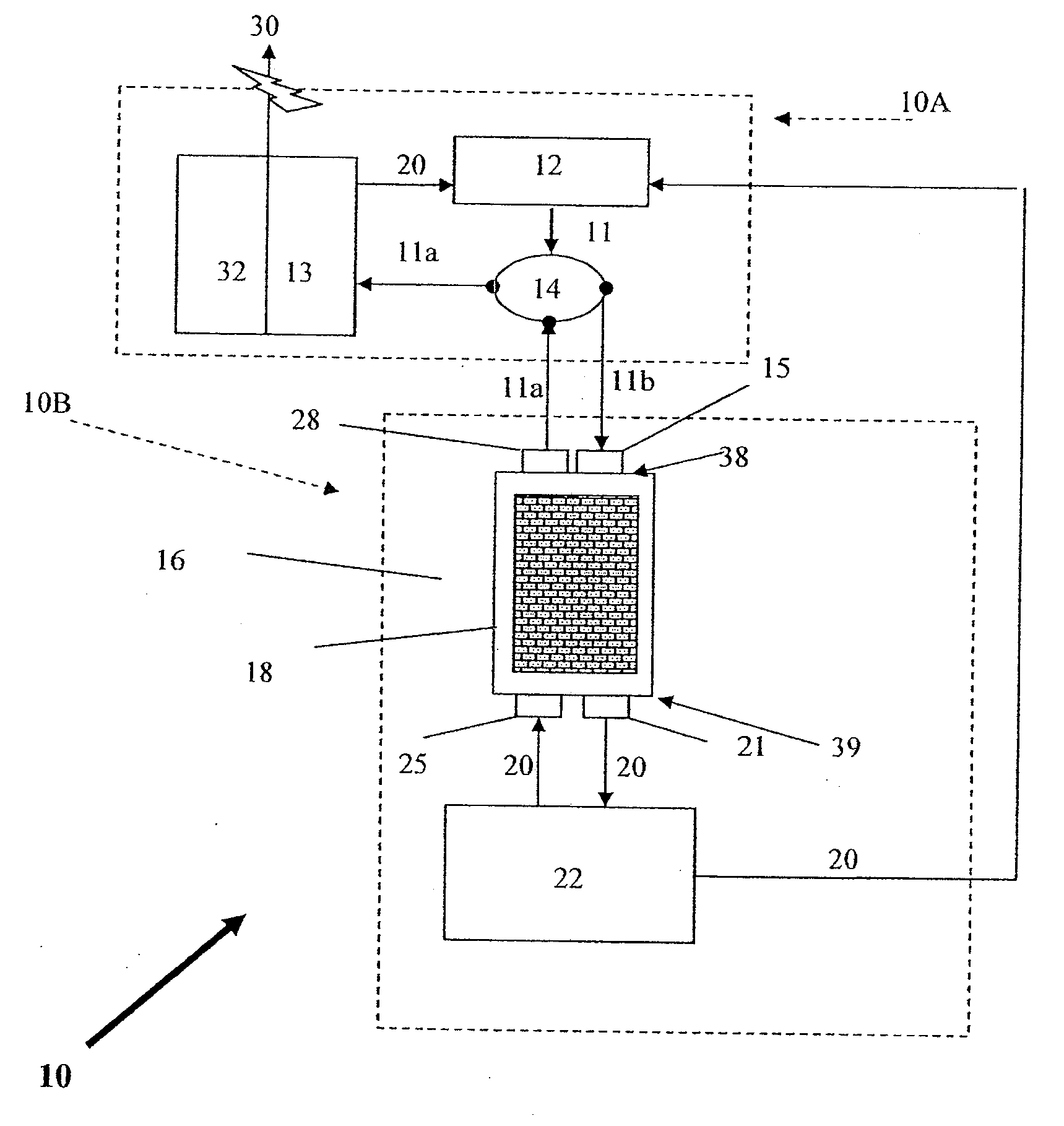
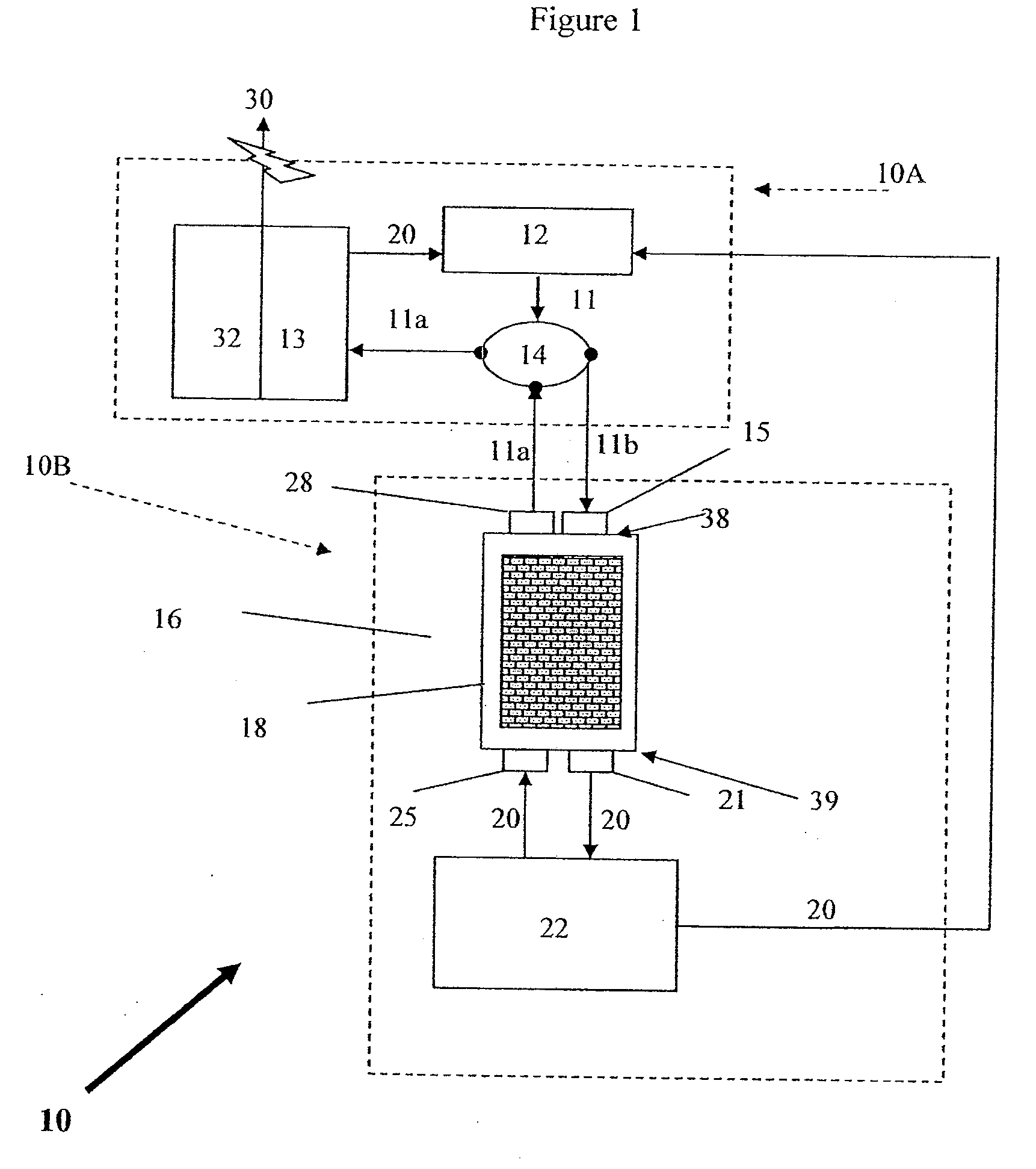
[0015]The present invention provides method and apparatus for storing heat, most notably in industrial systems where large sources of stored energy are called upon to meet a work load, such as for driving a turbine in electric power generating plants. The present invention overcomes thermal storage limitations and in fact enables storage of heat at practically any temperature at which most power plants can operate. The present invention is simple in design and is more robust and is relatively less expensive to implement and operate than other methods of heat storage for large-scale applications.

Problems solved by technology

But in size and cost, these are mostly small-scale applications.
But larger power applications cannot be adequately served with electro-chemical storage batteries.
But these large-scale applications cannot be cost-effectively served with electrochemical storage and yet hydro-electric storage capacity is limited to regions and local conditions.
But this causes a significant loss in free energy as the obtained steam has a lower temperature and pressure, and it is an expensive method with low thermal efficiency.
Pumped storage, which is similar to hydroelectricity, is widely practiced where the topology allows it but has only moderate efficiency.
Compressed air can also be used but it only has moderate efficiency and relatively high costs.
None are presently used to meet the large-scale demand in supporting the grid.
However, to be effective, this requires a large over-capacity compared to the average capacity of the plant.
But now power plants do not maintain such excess capacity.
However, demand has grown, and yet new plants have not been built at a rate to keep up with this growth.
Furthermore, while today coal power plants are more efficient than fifty years ago, still overall they have become more expensive to operate per kWh, as the need to reduce pollution has increased their cost dramatically.
Furthermore, at the same time that over-capacity of the grid has substantially decreased, the variability of grid operations has increased dramatically.
This has created a severe supply and control crisis.
Not only do we have new user technology, like air-conditioning that is more variable in its use and increases load considerably, but we now have new variable generation sources, such as wind turbine, solar cells, and concentrating solar power (CSP), that can cause dangerous swings on the grid.
While CSP power plants are large enough to make it economical and practical to be provided with large-scale storage, most notably molten salt, solar cells and wind cannot.
But building new power plants is a long process and is very expensive.
The problem is that gas turbines have a very low turndown ratio, losing efficiency very rapidly when power is below maximum.
But they are not suitable for rapid load following for grid regulation and there is not enough overcapacity to enable such operation as a practical matter.
One of IGCC's problems is that its turndown ratio is very low and so is its capability to rapidly load follow is low.

Method used


Image

  • Apparatus and method for storing heat energy
  • Apparatus and method for storing heat energy
  • Apparatus and method for storing heat energy

Examples


Embodiment Construction

[0030]The particulars shown herein are by way of example and for purposes of illustrative discussion of the embodiments of the present invention only and are presented in the cause of providing what is believed to be the most useful and readily understood description of the principles and conceptual aspects of the present invention. In this regard, no attempt is made to show structural details of the present invention in more detail than is necessary for the fundamental understanding of the present invention, the description taken with the drawings making apparent to those skilled in the art how the several forms of the present invention may be embodied in practice.

[0031]Unless otherwise stated, a reference to a compound or component includes the compound or component by itself, as well as in combination with other compounds or components, such as mixtures of compounds. As used herein, the singular forms “a,”“an,” and “the” include the plural reference unless the context clearly dic...


PUM


Abstract

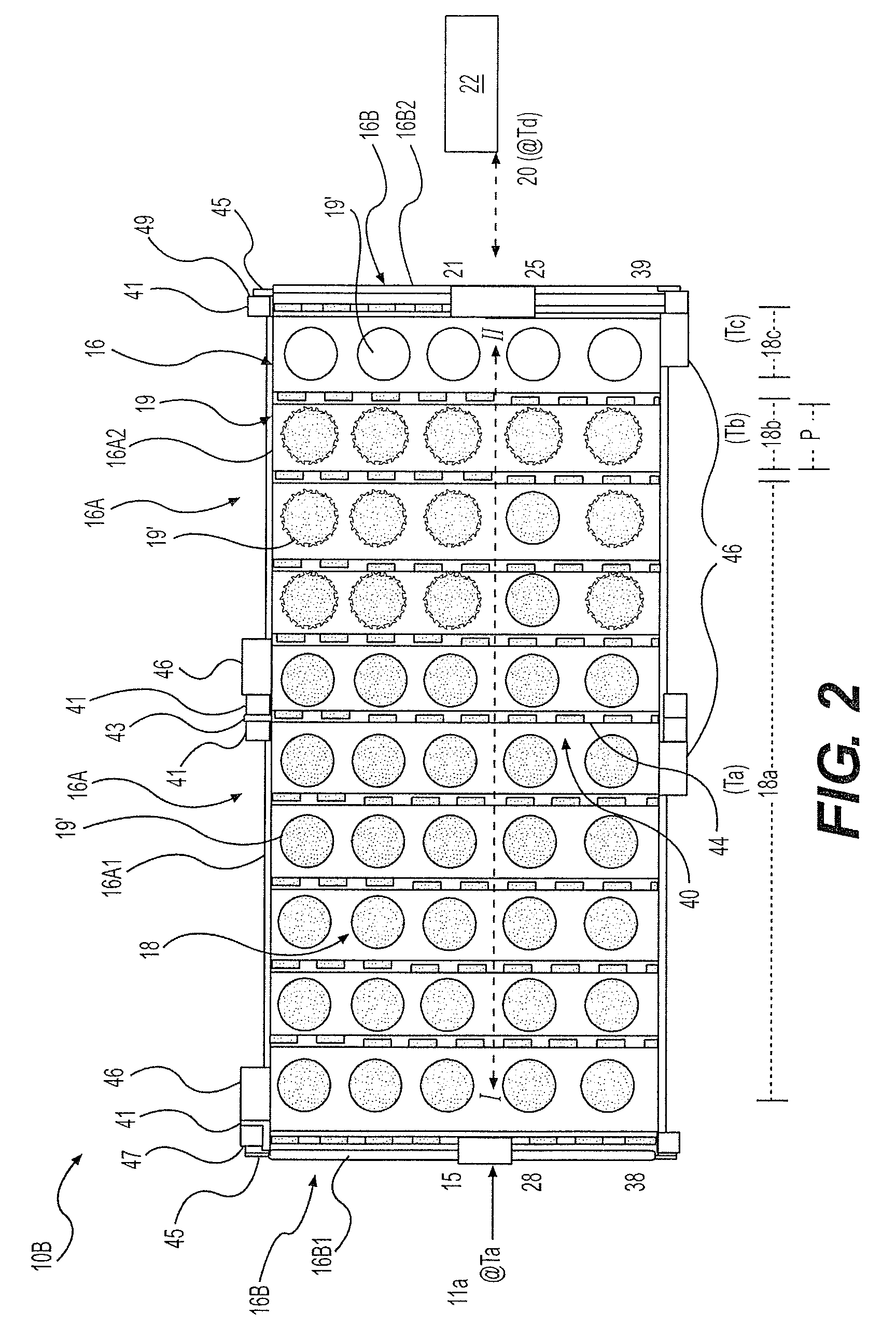
Method and apparatus for storing heat in industrial systems where large sources of stored energy are called upon to meet a work load, storing the heat content of a hot working fluid by using the hot working fluid as a heat transfer fluid in vapor form and depositing its heat content on a heat storage medium and then removing the cooled and condensed liquid phase of that heat transfer fluid, and when hot working fluid again is needed, the liquid heat transfer fluid is returned to the heated storage medium and is reheated as it passes through the hot storage medium and then is returned to the working system to be used as a hot working fluid.

Description

CROSS-REFERENCE TO RELATED APPLICATIONS[0001]The present application claims the benefit of priority of Patent Applications under 35 U.S.C. § 119(e) of Ser. No. 61 / 063,467, filed Jan. 31, 2008, Ser. No. 61 / 069,778, filed Mar. 17, 2008, Ser. No. 61 / 069,779, filed Mar. 17, 2008, Ser. No. 61 / 097,043, filed Sep. 15, 2008, Ser. No. 61 / 083,005, filed Jul. 23, 2008, Ser. No. 61 / 083,051, filed Jul. 23, 2008, Ser. No. 61 / 086,055, filed Aug. 4, 2008, Ser. No. 61 / 115,831, filed Nov. 18, 2008, Ser. No. 61 / 008,635, filed on Dec. 21, 2007, the disclosures of which are expressly incorporated by reference herein in their entirety. The present application is also a Continuation-in-Part of application Ser. No. 12 / 066,054, filed on Mar. 6, 2008, which is the national stage of International Application SN# PCT / US07 / 74646, filed on Jul. 27, 2007, which claims the benefit of priority under 35 U.S.C. 119(e) of Application Ser. No. 60 / 905,729, filed on Mar. 8, 2007, and is also a Continuation-in-Part of Int...

Claims


Application Information

Patent Timeline
IPC IPC(8): F01K3/00
CPCF01K3/00F01K23/10Y02E20/16F28D20/0056Y02E60/142Y02E20/18F28D17/005Y02E60/14
Inventor SHINNAR, REUEL
Owner RES FOUND THE CITY UNIV OF NEW YORK
Learn More