Cooled aerofoil blade or vane

Active Publication Date: 2011-03-10
ROLLS ROYCE PLC
View PDF4 Cites 9 Cited by
  • Summary
  • Abstract
  • Description
  • Claims
  • Application Information

AI Technical Summary

Benefits of technology

[0011]The first local thickening of the divider member may be greater along the centre line of the divider member than along the edges of the divider member where the divider member connects with the wall parts. By increasing the thickening of the divider member along its centre line, the contraction of the flow in a region midway between the facing wall parts can be made to occur earlier than the contraction which occurs where the divider member meets those wall parts. As an effect of symmetric secondary flows, the middle region of the first passage portion typically has less momentum or less attached flow compared to the side regions. The differential thickening of the divider member can control the flow momentum locally.
[0012]More specifically, without this increased thickening along the centre line, the flow attached to the wall parts can overturn because boundary layers at the wall parts tend to cause the flow to have less momentum than the flow away from the wall parts. Overturning of the flow can produce a pair of counter-rotating vortices. However, the thickening along the centre line produces turning of the flow towards the wall parts in the opposite sense to the counter-rotating pair, and thus helps to eliminate or reduce the strength of such vortices. In addition, the thickening along the centre line helps to increase the radius of curvature of the divider member around the bend passage portion, which can reduce a tendency for the flow to separate from the surface of the divider member after the bend

Problems solved by technology

Unfortunately, as the cooling fluid flows round the bends, it experiences a drop in pressure, which can be particularly large where a bend subtends a large angle (eg 180°.
Such pressure drops can be problematic if, for example, the cooling fluid is subsequently required for film cooling of an external surface of the

Method used


Image

  • Cooled aerofoil blade or vane
  • Cooled aerofoil blade or vane
  • Cooled aerofoil blade or vane

Examples


Example

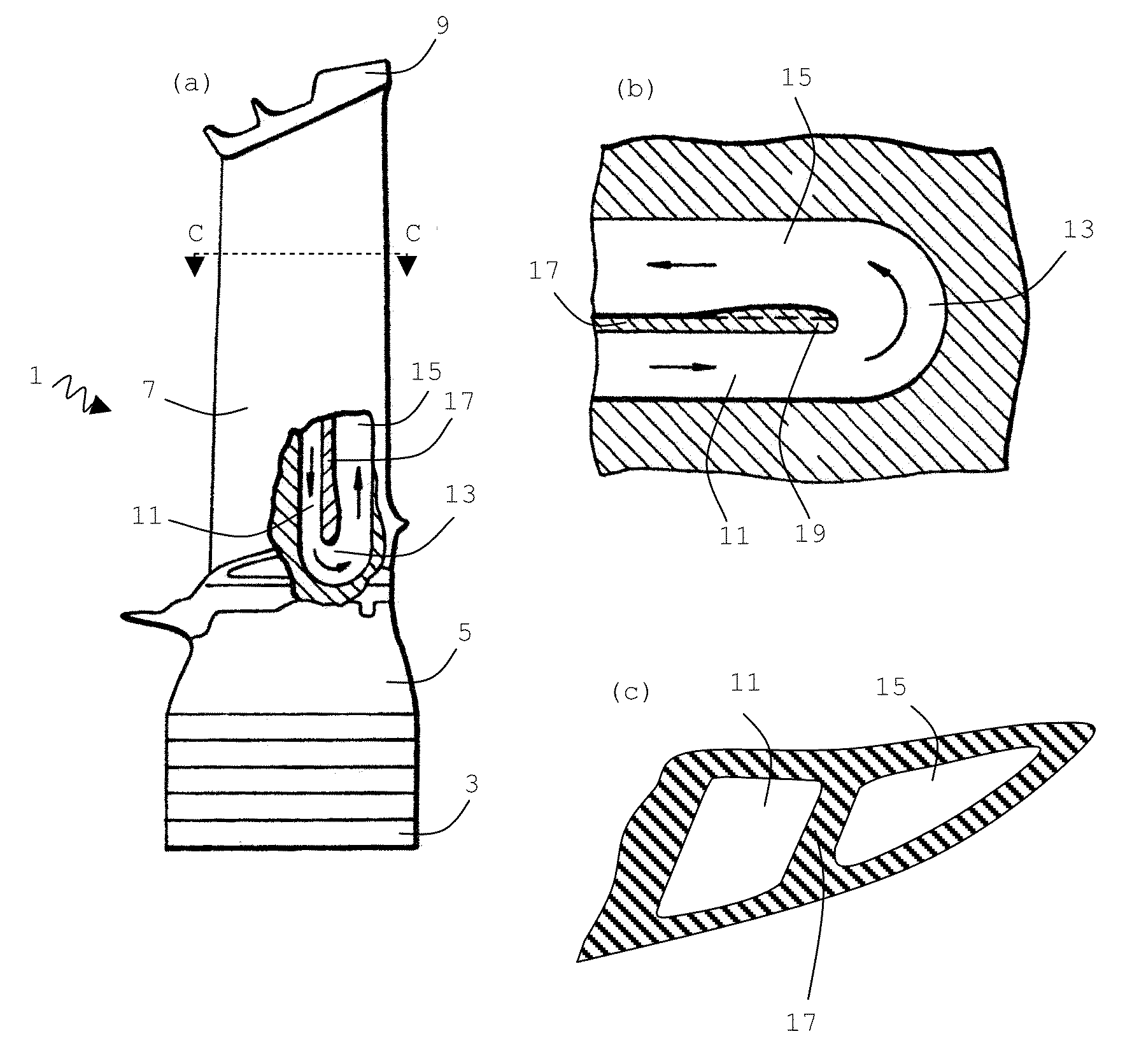
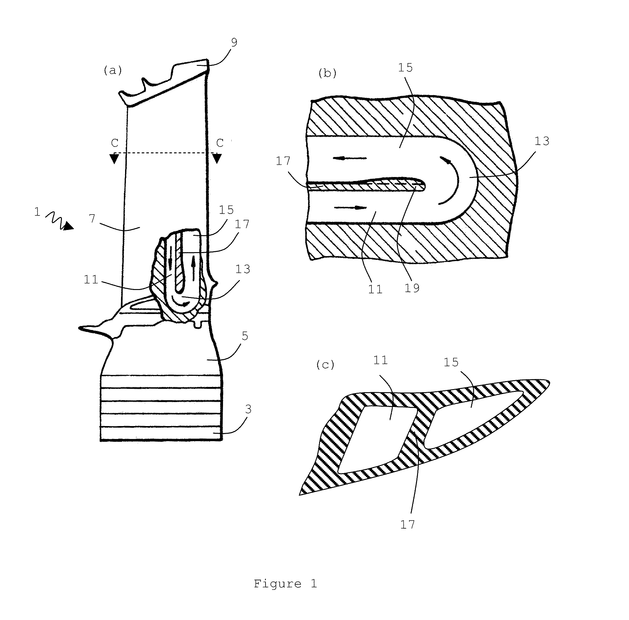
[0033]FIG. 1(a) shows a conventional aerofoil blade 1 for the high pressure turbine of a gas turbine engine. The blade is mounted with a plurality of similar blades on the periphery of a disc which rotates within the gas turbine engine. The blade comprises a root portion 3 for attachment to the disc. A platform 5 is located radially outward of the root portion, and an aerofoil portion 7 is located radially outward of the platform. A shroud portion 9 is located on the radially outmost extent of the aerofoil portion. The shroud and platform serve to define a portion of the turbine gas passage in which the aerofoil portion is located. Since the gases which flow over the aerofoil portion are usually at very high temperature, the aerofoil portion has interior passages through which a coolant, typically air, can circulate. The air flows through the passages before being ejected from the blade. The arrows show the direction of flow through the passages.

[0034]In order to cool the blade effe...


PUM


Abstract

An aerofoil blade or vane (1) suitable for the turbine of a gas turbine engine includes a longitudinally extending aerofoil portion (7) having facing wall parts (20, 22). The wall parts being interconnected by a generally longitudinally extending divider member (17) to partially define first and second cooling fluid passage portions (11, 15) disposed in side-by-side generally longitudinally extending relationship. The first and second passage portions being interconnected in series fluid flow relationship by a bend passage portion (13). The first passage portion is adapted to direct cooling fluid to the bend portion and the second passage portion being adapted to exhaust cooling fluid from the bend portion. The divider member has a first local thickening (33) in the region of the bend portion to provide a localised contraction of the downstream end of the first passage portion to accelerate the cooling fluid flow before it enters the bend passage portion. The divider member has a second local thickening (31) in the region of the bend portion to provide a localised progressive series narrowing and opening of the upstream end of the second passage portion in the general direction of cooling fluid flow.

Description

FIELD OF THE INVENTION[0001]The present invention relates to a cooled aerofoil blade or vane for use in gas turbine engines.BACKGROUND OF THE INVENTION[0002]The turbines used in modern gas turbine engines are required to operate at extremely high temperatures. In order for the aerofoil blades or vanes present in those turbines to withstand such high temperatures, it is necessary to cool them. This is typically achieved by providing the blades or vanes with internal passages, through which a cooling fluid, usually air, can be passed.[0003]In order to maximise the efficiency of heat transfer from a blade or vane to the cooling fluid, a single passage may pass through the blade or vane several times. This will inevitably mean that the passages have bends around which the cooling fluid must flow. Unfortunately, as the cooling fluid flows round the bends, it experiences a drop in pressure, which can be particularly large where a bend subtends a large angle (eg 180°. Such pressure drops c...

Claims


Application Information

Patent Timeline
IPC IPC(8): F01D5/18
CPCF01D5/187F05D2250/324F05D2270/17F05D2250/185
Inventor IRELAND, PETER T.NAMGOONG, HOWOONG
Owner ROLLS ROYCE PLC
Why Eureka
Try Eureka