Magnetic inductor rotary machine and fluid transfer apparatus that uses the same

a technology of magnetic inductor and rotary machine, which is applied in the direction of positive displacement liquid engine, synchronous motor, pump, etc., can solve the problems of axial resonance and interference between the bearing and the coil end of the stator coil, and achieve the effect of reducing the magnetic resistance between the rotor and the stator, and reducing the amount of magnetic flux

Active Publication Date: 2011-03-10
MITSUBISHI ELECTRIC CORP
View PDF24 Cites 26 Cited by
  • Summary
  • Abstract
  • Description
  • Claims
  • Application Information

AI Technical Summary

Benefits of technology

[0016]According to the present invention, because a salient pole width βr of salient poles of a first rotor core and a second rotor core is configured so as to be greater than an opening width Os of slots of a stator, the rotor rotates in a state such that the salient poles always face the teeth of the stator. Thus, magnetic resistance between the rotor and the stator can be kept low, and fluctuations in the amount of magnetic flux kept to a minimum. Thus, fluctuations in the amount of magnetic flux that flows axially through the rotary machine are suppressed, and core loss that results from the occurrence of eddy currents is reduced, enabling a high-efficiency rotary machine to be achieved.

Problems solved by technology

However, in motors that are used in “electrically assisted turbochargers” in which the motor is disposed between a turbine and a compressor of an automotive supercharger, super-high-speed rotation that exceeds 100,000 revolutions per minute is required, and since they are used in high-temperature environments, problems with magnet holding strength, thermal demagnetization, etc., arise if conventional permanent magnet synchronous rotary machines are used in these motors.
In conventional magnetic inductor rotary machines, because a rotating shaft of the rotor is rotatably supported by bearings that are disposed at two axial ends of the rotor, “axial resonance”, in which the rotating shaft constitutes a resonance system and flexes and vibrates, is problematic.
Consequently, if the bearings are disposed radially inside the coil ends of the stator coil, problems of interference between the bearings and the coil ends of the stator coil arise.

Method used


Image

  • Magnetic inductor rotary machine and fluid transfer apparatus that uses the same
  • Magnetic inductor rotary machine and fluid transfer apparatus that uses the same
  • Magnetic inductor rotary machine and fluid transfer apparatus that uses the same

Examples


embodiment 1

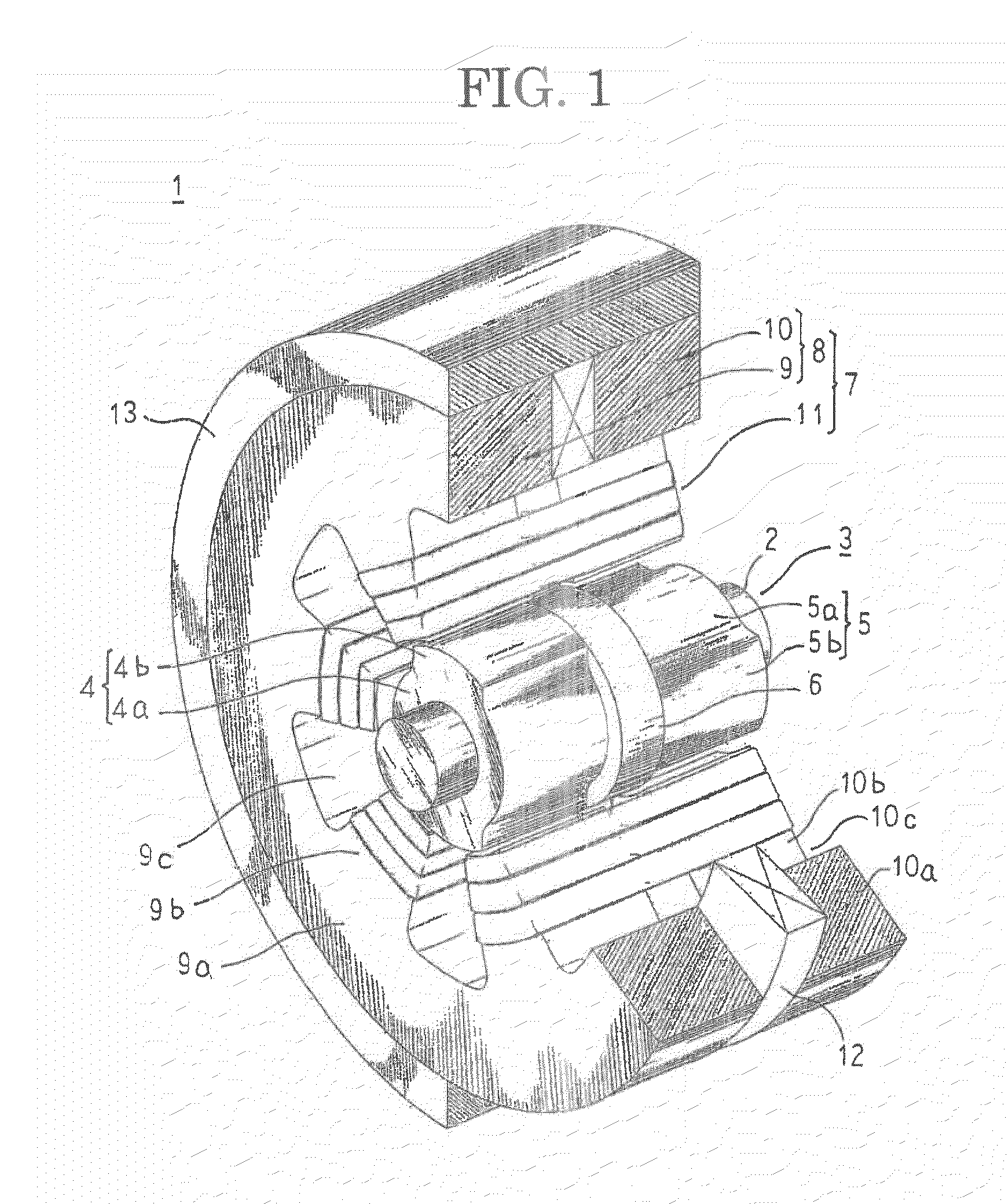
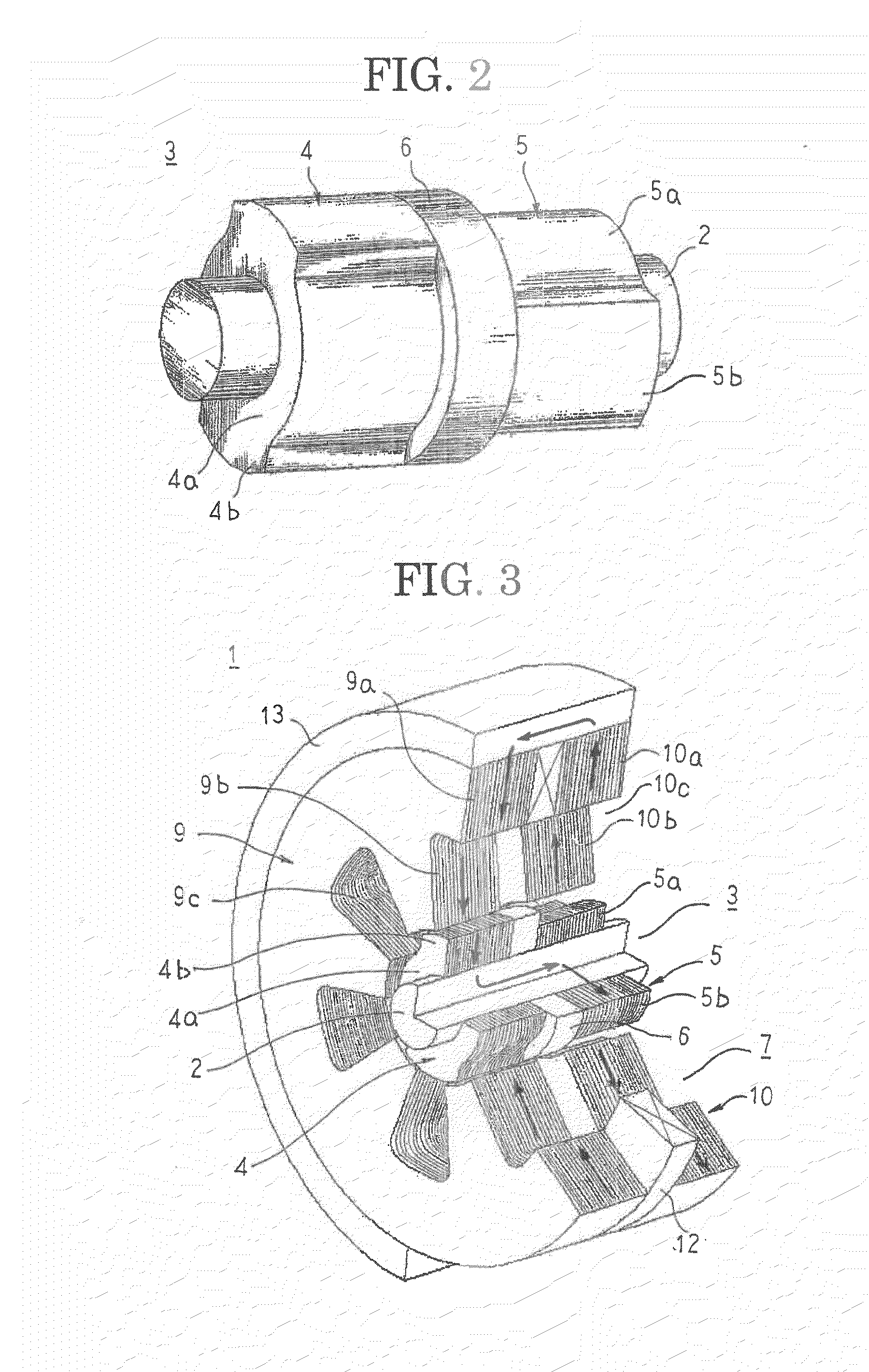
[0028]FIG. 1 is a partially cut away perspective that shows a configuration of a rotary machine according to Embodiment 1 of the present invention, and FIG. 2 is a perspective that shows a configuration of a rotor that can be used in the rotary machine according to Embodiment 1 of the present invention.

[0029]In FIGS. 1 and 2, a rotary machine 1 is a magnetic inductor synchronous rotary machine, and includes: a rotor 3 that is fixed coaxially to a rotating shaft 2 that is prepared using a solid magnetic body of iron, etc.; a stator 7 that is formed by mounting a stator coil 11 that functions as a torque generating driving coil to a stator core 8 that is disposed so as to surround the rotor 3; a field coil 12 that functions as a field means; and a housing 16 that houses the rotor 3, the stator 7, and the field coil 12.

[0030]The rotor 3 includes: first and second rotor cores 4 and 5 that are prepared, for example, by laminating and integrating a large number of magnetic steel plates th...

embodiment 2

[0063]FIG. 8 is a partially cut away perspective that shows a rotary machine according to Embodiment 2 of the present invention. Moreover, a stator coil has been omitted in FIG. 8.

[0064]In FIG. 8, a first stator core 9A includes: a cylindrical core back 9a; and six teeth 9b that are disposed so as to project radially inward from an inner peripheral surface of the core back 9a at a uniform angular pitch circumferentially. Flange portions 9d are disposed so as to extend in two circumferential directions from inner peripheral end portions of the teeth 9b to reduce opening widths of the slots 9c. A second stator core 10A is prepared into an identical shape to the first stator core 9A, and flange portions 10d are disposed so as to extend in two circumferential directions from inner peripheral end portions of teeth 10b to reduce opening widths of slots 10c.

[0065]Moreover, the rest of the configuration is configured in a similar manner to Embodiment 1 above.

[0066]In a rotary machine 1A th...

embodiment 3

[0069]FIG. 9 is a partially cut away perspective that shows a rotary machine according to Embodiment 3 of the present invention. Moreover, a stator coil has been omitted in FIG. 8.

[0070]In FIG. 9, a first permanent magnet 41 that functions as a magnetic field means is interposed in a state of close contact between a core back 9a of a first stator core 9A and an outer peripheral surface of a housing 13, and is magnetically oriented such that a direction of magnetization 43 is oriented radially inward. A second permanent magnet 42 that functions as a magnetic field means is interposed in a state of close contact between a core back 10a of a second stator core 10A and an outer peripheral surface of a housing 13, and is magnetically oriented such that a direction of magnetization 43 is oriented radially outward.

[0071]Moreover, the rest of the configuration is configured in a similar manner to Embodiment 2 above.

[0072]A rotary machine 1B that is configured in this manner, operates in a s...


PUM


Abstract

A high-efficiency magnetic inductor rotary machine in which eddy current loss is reduced even if driven at super-high-speed rotation, and a fluid transfer apparatus that uses the same. In the magnetic inductor rotary machines, first and second stator cores are disposed coaxially such that circumferential positions of teeth are aligned, and first and second rotor cores are fixed coaxially to a rotating shaft such that salient poles are offset by a pitch of half a salient pole circumferentially, and are disposed on an inner peripheral side of the first and second stator cores. A salient pole width of the salient poles of the first and second rotor cores is configured so as to be greater than an opening width of slots of a stator.

Description

TECHNICAL FIELD[0001]The present invention relates to a magnetic inductor rotary machine suitable for being driven in a high-speed rotation region where core loss components are dominant in motor loss, and to a fluid transfer apparatus that uses the same.BACKGROUND ART[0002]In conventional permanent magnet synchronous rotary machines, magnets that function as a magnetic field means are mounted to a rotor. However, in motors that are used in “electrically assisted turbochargers” in which the motor is disposed between a turbine and a compressor of an automotive supercharger, super-high-speed rotation that exceeds 100,000 revolutions per minute is required, and since they are used in high-temperature environments, problems with magnet holding strength, thermal demagnetization, etc., arise if conventional permanent magnet synchronous rotary machines are used in these motors.[0003]In consideration of these conditions, conventional magnetic inductor rotary machines have been proposed in w...

Claims


Application Information

Patent Timeline
Patent Type & Authority Applications(United States)
IPC IPC(8): F04B35/04H02K21/02H02K19/02
CPCH02K1/145H02K16/00H02K2201/12H02K19/103H02K29/03H02K16/02
Inventor ARITA, HIDEAKIINOUE, MASAYAIEZAWA, MASAHIROMIYAKE, TOSHIHIKO
Owner MITSUBISHI ELECTRIC CORP
Why Eureka
Try Eureka