Rotary electrical machine having permanent magnet rotor

Inactive Publication Date: 2016-03-03
EBARA CORP
View PDF1 Cites 4 Cited by
  • Summary
  • Abstract
  • Description
  • Claims
  • Application Information

AI Technical Summary

Benefits of technology

The patent describes a way to prevent the rotor in a rotary electrical machine from getting too hot and melting down. This is done by increasing the magnetic resistance between the windings and the rotor, which reduces the amount of leakage flux that passes through the rotor core and permanent magnets. This prevents a local overheating of both ends of the rotor, even when the machine is running at a high speed.

Problems solved by technology

In addition, the protective cover 105, disposed at the outside of the permanent magnet 104, is locally overheated, possibly causing dangerous situations, such as a decrease in a capability of fixing the permanent magnet 104 due to a degradation of the protective cover 105, an occurrence of dynamic unbalance of the rotor 100 due to a heat dissipation of resin that forms the protective cover 105, and an occurrence of vibration due to the unbalance.

Method used


Image

  • Rotary electrical machine having permanent magnet rotor
  • Rotary electrical machine having permanent magnet rotor
  • Rotary electrical machine having permanent magnet rotor

Examples


Embodiment Construction

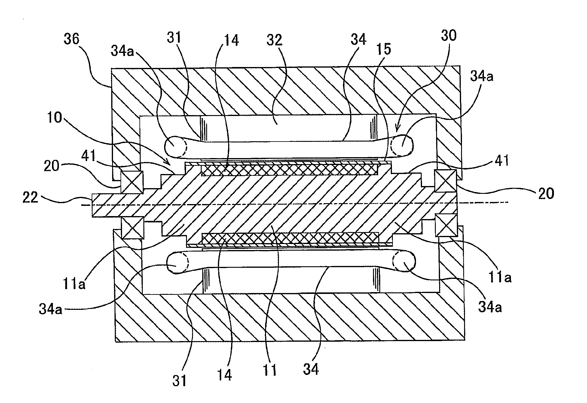
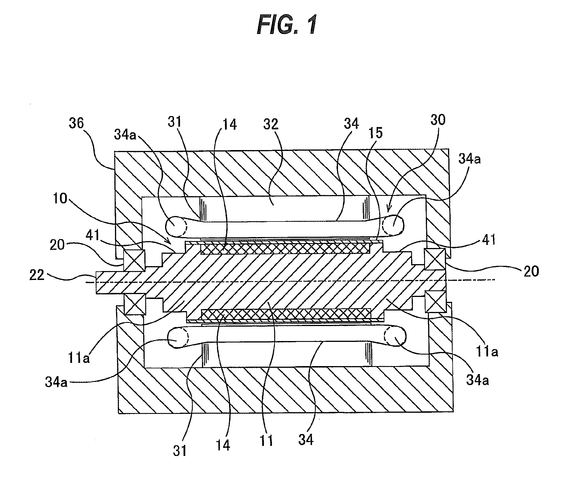
[0028]Embodiments will be described below with reference to the drawings. FIG. 1 is a cross-sectional view showing a SPM (Surface Permanent Magnet) rotary electrical machine according to an embodiment. In this specification, the rotary electrical machine is a general term for an electric motor and an electric generator. The rotary electrical machine according to the embodiment is a high-speed electric motor or electric generator whose rated speed is at least 10,000 min−1.

[0029]As shown in FIG. 1, a rotor 10 includes a rotor core 11 made of a magnetic material, and a plurality of permanent magnets 14 arranged on an outer surface of the rotor core 11. A protective cover 15, which is made of a fiber-reinforced resin or the like, is disposed outside of the permanent magnets 104, so that outer surfaces of the permanent magnets 104 are covered with the protective cover 15. This protective cover 15 serves to prevent the permanent magnets 14 from coming off the rotor 10 when the rotor 10 is...


PUM

PropertyMeasurementUnit
Lengthaaaaaaaaaa
Magnetic flux densityaaaaaaaaaa

Abstract

A rotary electrical machine capable of preventing an increase in a magnetic flux density at both ends of a rotor that can occur due to a leakage flux to thereby prevent a local overheat of the rotor is disclosed. The rotary electrical machine includes: a rotor having a rotor core and permanent magnets disposed on an outer surface of the rotor core; a stator having windings arranged around the rotor; and a shaft which is rotatable together with the rotor. The rotor core is a solid rotor core having a solid structure, the rotor core has protrusions at both sides of each of the permanent magnets, and annular recesses, extending in a circumferential direction of the rotor, are formed on outer surfaces of the protrusions, respectively.

Description

CROSS REFERENCE TO RELATED APPLICATION[0001]This document claims priority to Japanese Patent Application Number 2014-177416 filed Sep. 1, 2014, the entire contents of which are hereby incorporated by reference.BACKGROUND[0002]An SPM (Surface Permanent Magnet) rotor, which has permanent magnets arranged on a surface of a rotor core, has been known as a permanent magnet rotor used in a rotary electrical machine, such as an electric motor or an electric generator. FIG. 6 is a schematic view showing an example of the SPM rotor. The rotor 100 includes a rotor core 101 made of magnetic material, and a plurality of permanent magnets 104 arranged on an outer surface of the rotor core 101. A protective cover 105, which may be made of fiber-reinforced resin, is disposed outside of the permanent magnets 104, so that outer surfaces of the permanent magnets 104 are covered with the protective cover 105. This protective cover 105 serves to prevent the permanent magnets from coming off the rotor 1...

Claims


Application Information

Patent Timeline
IPC IPC(8): H02K1/27
CPCH02K1/2786H02K1/278H02K3/42C23C24/085H02K21/14
Inventor YOSHIDA, KAZUTAKAKATAOKA, TADASHI
Owner EBARA CORP
Why Eureka
Try Eureka