Ultrasonic bonding method of electric wire

a technology of ultrasonic bonding and electric wire, which is applied in the direction of soldering apparatus, manufacturing tools, and capacitors, can solve problems such as electrical trouble, and achieve the effects of suppressing swelling of core wires along side walls, and effectively suppressing swelling of core wires

Active Publication Date: 2011-03-17
YAZAKI CORP
View PDF21 Cites 34 Cited by
  • Summary
  • Abstract
  • Description
  • Claims
  • Application Information

AI Technical Summary

Benefits of technology

[0010]That is, the cross section of the conductor end molded by press is formed so that the thickness of the direction set between the side walls of the connection terminal and pushed becomes thin toward the sides of the side walls. Therefore, even when the conductor end becomes deformed so as to spread in the width direction between the side walls at the time of applying the ultrasonic vibration, the amount of the core wires pushed on the side walls becomes small as the thickness of the sides of the side walls of the conductor end becomes thin, so that swelling of the core wires along the side walls can be suppressed.
[0011]Concretely, in the cross section of the conductor end of the electric wire, at least one of the side positioned in the bottom surface and the side to which the ultrasonic vibration is applied can be formed in, for example, a trapezoidal shape or a semicircular shape. Such shapes can simply be formed by press molding and thicknesses of both the shapes become thin toward the sides of the side walls, so that swelling of the core wires can be suppressed effectively. Further, the cross section of the conductor end may be formed by combining different shapes, for example, the side to which the ultrasonic vibration is applied is formed in the trapezoidal shape and the side positioned in the bottom surface is formed in the semicircular shape.
[0012]According to the invention, swelling of the core wire can be suppressed in the case of performing ultrasonic bonding of the conductor end to the connection terminal.

Problems solved by technology

The core wires swelling to the position higher than the side walls thus, for example, tend to become an obstacle in the case of insertion into a housing into which the connection terminal is inserted, and may also cause electrical trouble such as a short circuit in the case of having a deficiency of the core wires.

Method used


Image

  • Ultrasonic bonding method of electric wire
  • Ultrasonic bonding method of electric wire
  • Ultrasonic bonding method of electric wire

Examples


Embodiment Construction

[0024]One embodiment of an ultrasonic bonding method of an electric wire made by applying the invention will hereinafter be described with reference to the drawings.

[0025]In the present embodiment, an electric wire in which a conductor end made of plural core wires is exposed, a press metal mold by which the conductor end of this electric wire is molded by press, a connection terminal to which the conductor end is bonded, and an ultrasonic bonding apparatus for bonding the conductor end to the connection terminal are used.

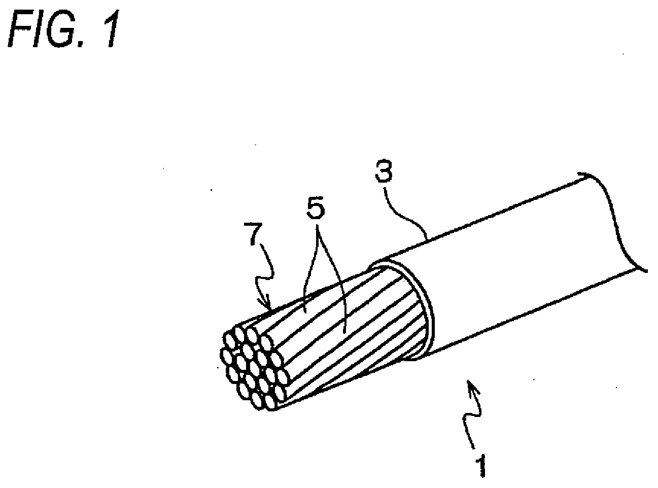
[0026]As shown in FIG. 1, an electric wire with plural core wires 5 (hereinafter called a conductor end 7) exposed from an insulating outer skin 3 is prepared for an electric wire 1. In this electric wire 1, the conductor end 7 is molded by press by the press metal mold.

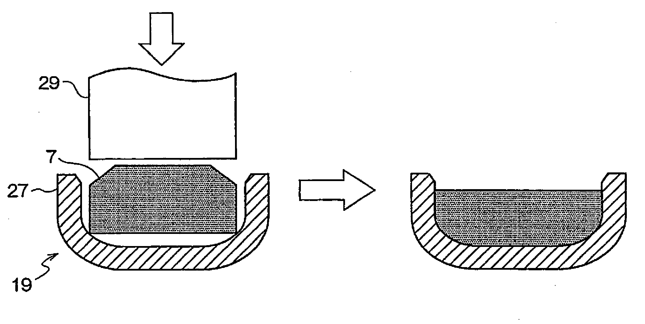
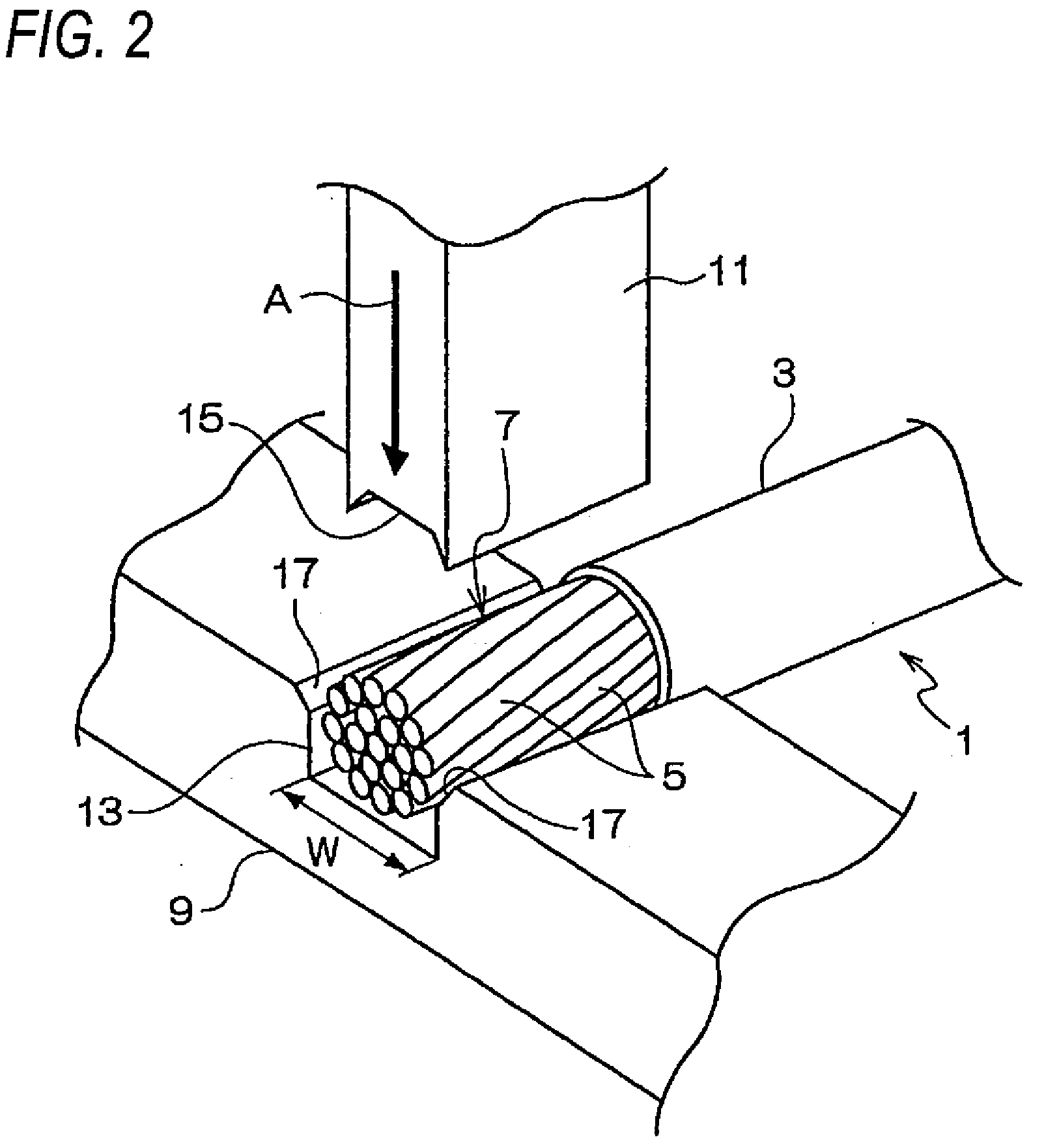
[0027]The press metal mold includes a lower mold 9 and an upper mold 11 as shown in FIG. 2. A groove 13 in which the conductor end 7 of the electric wire 1 is received is formed in the lower mold 9....


PUM

PropertyMeasurementUnit
thicknessaaaaaaaaaa
metallicaaaaaaaaaa
adhesionaaaaaaaaaa

Abstract

In an ultrasonic bonding method of an electric wire in which the electric wire 1 in which a conductor end 7 made of plural core wires is exposed and a metallic connection terminal 19 formed by erecting two side walls 27 from a bottom surface are prepared and the conductor end is bonded to the connection terminal by applying ultrasonic vibration while the conductor end of the electric wire is positioned in the bottom surface between the two side walls of the connection terminal and is pushed, a cross section of the conductor end of the electric wire is made by being molded by press so that a thickness of a width direction between the side walls becomes thin toward at least one of the side positioned in the bottom surface of the connection terminal and the side to which the ultrasonic vibration is applied.

Description

BACKGROUND[0001]1. Field of the Invention[0002]The present invention relates to an ultrasonic bonding method of an electric wire in which ultrasonic bonding of a conductor part of the electric wire made of plural core wires is performed to a metallic terminal.[0003]2. Description of the Related Art[0004]An ultrasonic bonding method is known conventionally as a method for connecting a conductor part of an electric wire to a metallic terminal. As one example of this ultrasonic bonding method, for example, a method in which an electric wire in which a conductor end made of plural core wires is exposed from an insulating outer skin and a connection terminal formed by erecting two side walls from a bottom surface are prepared and after the conductor end of the electric wire is first molded by press in a flat shape (flat plate shape), ultrasonic vibration is applied while this conductor end molded by press is positioned in the bottom surface between the two side walls of the connection te...

Claims


Application Information

Patent Timeline
Patent Type & Authority Applications(United States)
IPC IPC(8): B23K20/10
CPCB23K20/106B23K2201/38H01R43/0207H01R4/187H01R4/185B23K2101/38
Inventor OHNUMA, KENTARO
Owner YAZAKI CORP
Why Eureka
Try Eureka