System and method for creating multizones from a single zone heating system

a heating system and multi-zone technology, applied in the field of heating and cooling systems, can solve the problems of inability to have different temperatures in different rooms, and inability to achieve multi-zone heating

Inactive Publication Date: 2011-03-17
KHALAFI ASGHAR
View PDF5 Cites 10 Cited by
  • Summary
  • Abstract
  • Description
  • Claims
  • Application Information

AI Technical Summary

Benefits of technology

The present invention features a method of converting a single zone system into a multizone system, wherein the method comprises the acts of retrofitting an existing heating element in at least a first and a second room by adding an input device at one end of the heating element, the input device coupled to an existing hot water pipe on a first end and to the heating element on a second end, wherein the input device includes an RF circuit configured for receiving an RF control signal from a thermostat; installing a bypass pipe, coupled to the input device on the second end and generally providing a hot water path parallel to the heating element; installing an output device, the output device coupled proximate a first end to the bypass pipe and the heating element and coupled proximate a second send to an existing hot water pipe; installing a central thermostat in the first room, wherein the central thermostat comprises a temperature sensing device, temperature setting controls, an RF circuit and control wires to a boiler, the RF circuit for providing the input device RF control signal; and installing at least one peripheral thermostat in the second room, wherein the peripheral thermostat comprises a temperature sensing device, temperature setting controls, a display monitor and an RF circuit, the RF circuit for providing the input device RF control signal.
It is important to note that the present invention is not intended to be limited to a system or method which must satisfy one or more of any stated objects or features of the invention. It is also important to note that the present invention is not limited to the preferred, exemplary, or primary embodiment(s) described herein. Modifications and substitutions by one of ordinary skill in the art are considered to be within the scope of the present invention and are not to be limited except by the allowed claims and their legal equivalents.

Problems solved by technology

The problems with the current one zone systems are numerous.
This approach makes it impossible to have different temperatures in different rooms.
Another problem with this design is that a room that is drafty (not well insulated for example) will be colder that another room that is well insulated.
If the thermostat is located in a drafty room or an area where it is closer to a door that is used for outside access every time people enter or exit the temperature in that area will be affected.
This causes the call for heat to be premature which causes a big temperature difference between rooms on that floor.
An additional problem with this design is the fact that hot water entering the first room in the circuit is hotter than the hot water entering the last room in the circuit due to loss of heat as the water travels from room to room through the heating elements.
As a result, it is not possible in the standard one zone systems to maintain a constant temperature throughout all of the rooms in the zone and it is also not possible to raise or lower the temperature in one of the rooms within the zone independent of the temperature in the remaining rooms.
This type of system is seen in some homes, however this design can be prohibitively expensive.
In an already constructed home, it would be extremely costly to install a system like this due to the extensive renovations that would be needed to convert a single zone system to a multizone system of this style.

Method used


Image

  • System and method for creating multizones from a single zone heating system
  • System and method for creating multizones from a single zone heating system
  • System and method for creating multizones from a single zone heating system

Examples


Embodiment Construction

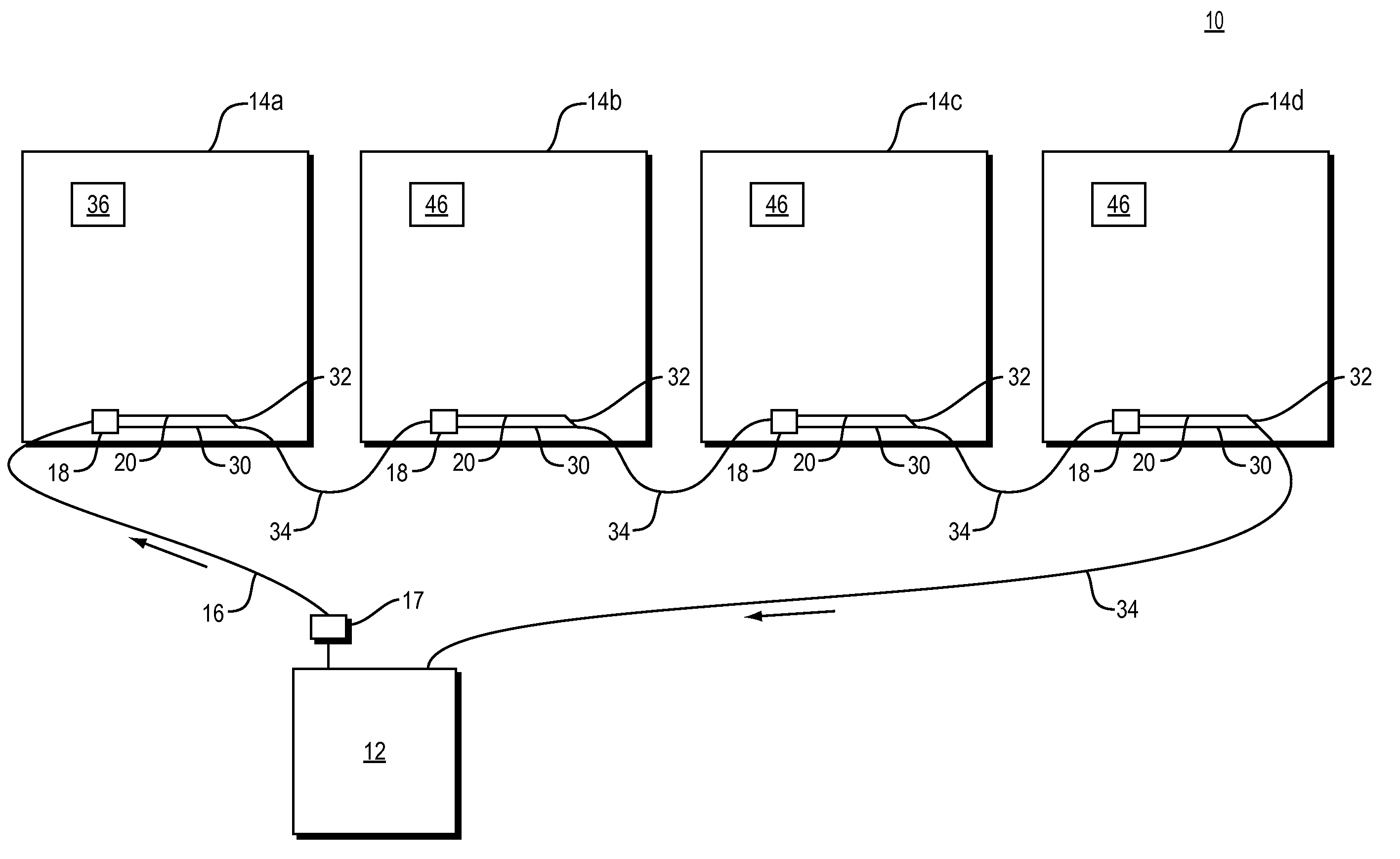
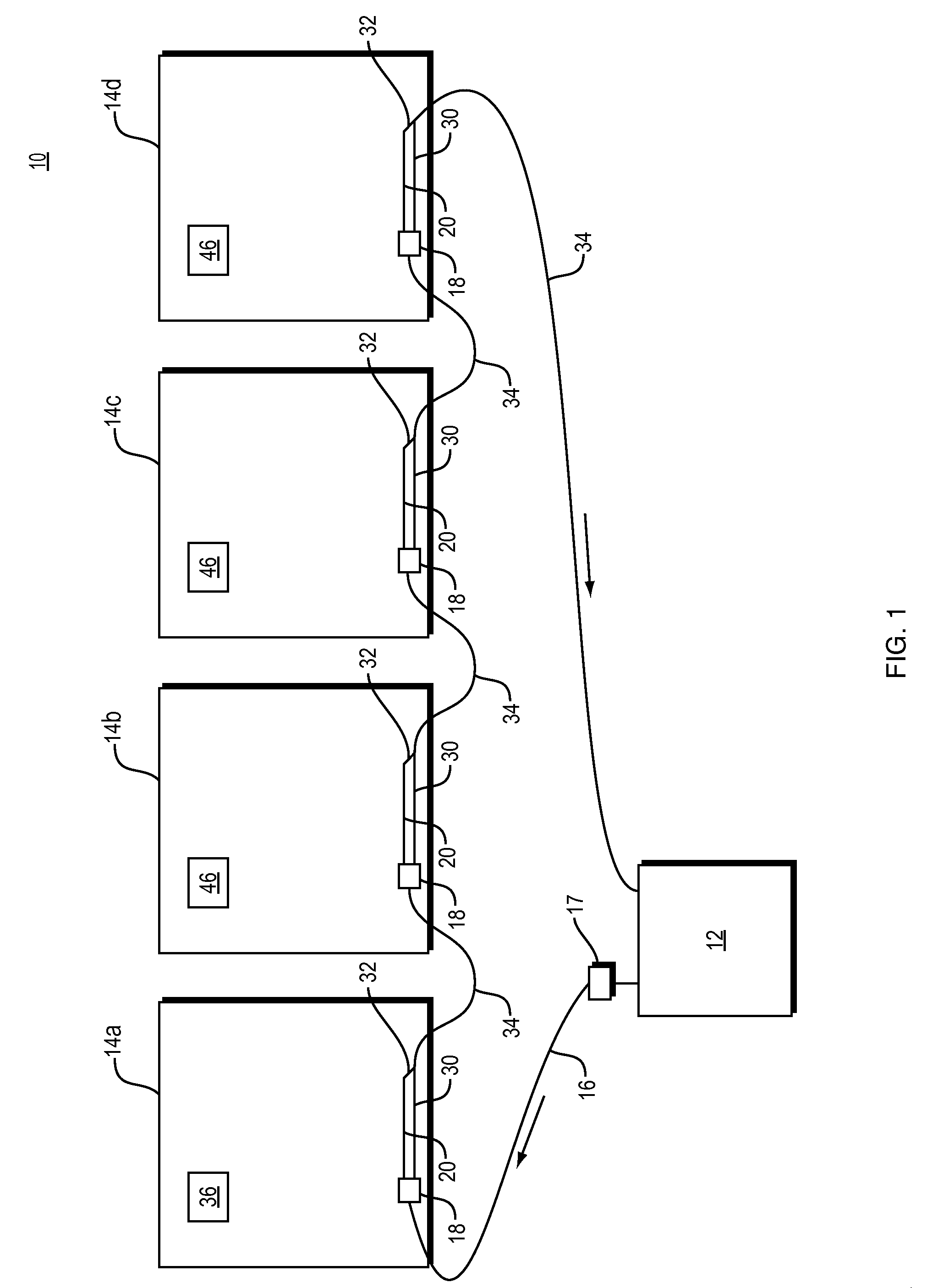
The present invention features a multizone conversion system 10 for a forced hot water single zone heating system. The multizone conversion system 10 allows a single zone consisting of multiple rooms or spaces to be divided into a plurality of zones, FIGS. 1 and 2. The multizone conversion system 10 can be installed into a new home or into an older home without the need for major renovations while allowing the existing heating system to be left intact. The multizone conversion system 10 involves designating each room (14a, 14b, 14c, 14d, etc.) within a single zone as its own “zone” without the need for additional wiring, new plumbing connections to the main boiler, or other costly construction costs. In a hot water system, the water is heated by a boiler, furnace or other heat generation system 12 and the water is sent to the first room 14a of the zone via a hot water output pipe 16.

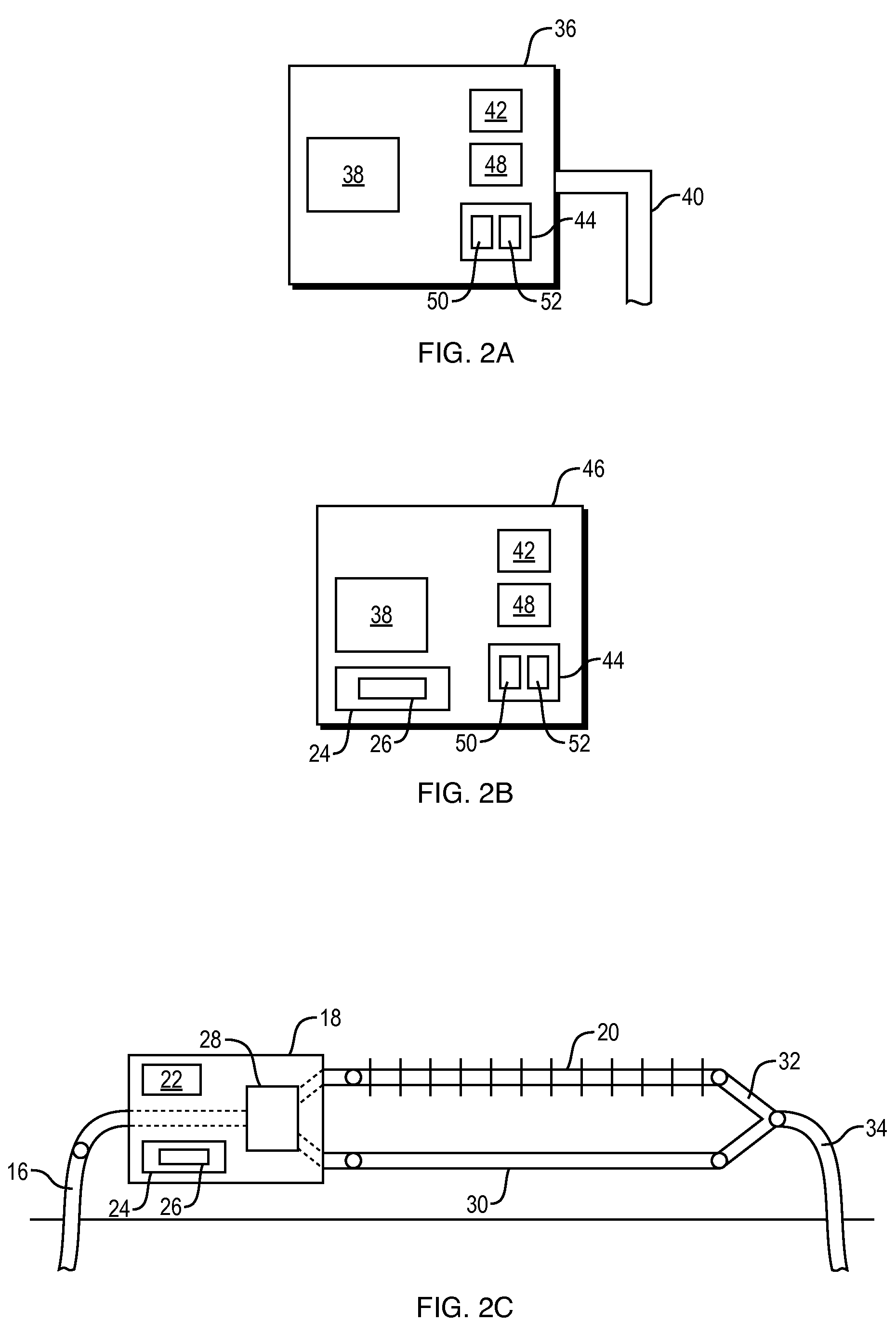
First, an input device 18 is installed inline with the hot water output pipe 16 in the first room of ...


PUM

PropertyMeasurementUnit
temperatureaaaaaaaaaa
heataaaaaaaaaa
temperaturesaaaaaaaaaa

Abstract

The present invention features a multizone conversion system for converting a single zone system into a multizone system. The multizone conversion system is designed to require minimal renovations and does not require extensive new wiring. Each room within the new multizone system has its own thermostat controls and each room can be set to its own specific temperature. The multizone conversion system does not require new piping to and from the boiler. Each thermostat is equipped with a temperature sensing device, temperature setting controls, an LCD monitor or display and an RF circuit that includes an RF transmitter and an RF receiver. Each heating element within the room is outfitted with an input device that contains an RF circuit, a switching valve and a battery compartment. The thermostat communicates wirelessly with the output device located in the room and control the flow of the heated water through the existing heating element or alternatively through a bypass pipe if heat is not required.

Description

TECHNICAL FIELDThe present invention relates to heating and cooling systems and more particularly, relates to systems and methods for converting single zone systems into multizone systems.BACKGROUND INFORMATIONThe majority of existing heating and / or cooling designs in homes and offices are designed as single or multiple zones. For example, in home design, typically an entire home or an entire floor of a home is designed to be in one zone. In this scenario, the temperature on the thermostat on the floor is set to a desired temperature. Once the temperature in the area where the thermostat is installed falls (or raises) below or above a set temperature, the thermostat sends a signal down to the boiler or air conditioner asking to start the heat or air conditioning to that floor. In the case of heat, the boiler starts heating up the water (to a set temp), opens up the valve to that floor and starts pumping the hot water up through that floor which passes through every room in that floo...

Claims


Application Information

Patent Timeline
Patent Type & Authority Applications(United States)
IPC IPC(8): G05D23/00B23P19/04
CPCF24D2220/042F24F2011/0067F24D19/0007Y10T29/49826F24F2011/0068F24D19/1021F24F11/0012F24F11/56F24F11/54F24F11/30F24F2110/10F24F11/84F24F11/523
Inventor KHALAFI, ASGHAR
Owner KHALAFI ASGHAR
Why Eureka
Try Eureka