Direct current electrical controls for heating systems

a technology of direct current and electrical control, which is applied in the direction of heating types, lighting and heating apparatus, transportation and packaging, etc., can solve the problems of inability to disclose dc control units, inability to control devices for heating systems, and inherently inefficient systems, etc., to reduce or eliminate the associated constant electrical demand of heating components, prolong battery life, and reduce the effect of reducing or eliminating

Inactive Publication Date: 2001-05-29
STICKNEY BRISTOL L +1
View PDF18 Cites 21 Cited by
  • Summary
  • Abstract
  • Description
  • Claims
  • Application Information

AI Technical Summary

Benefits of technology

Another advantage of the present invention is that it can eliminate both the AC transformers and zone valves, thereby eliminating the associated constant electrical demand of these components. This helps prolong battery life and can reduce or eliminate the need to run a backup generator to provide power for the heating system.
Yet another advantage of the present invention is that no internal modifications are required to any of the heating system equipment, so no special technical knowledge is needed for installation and maintenance, and original equipment warranties remain intact.
Another advantage of the present invention is that the use of DC zone pumps in place of conventional AC pumps with AC zone valves can provide a large savings in electrical consumption, which can further prolong battery life.
Yet another advantage of the present invention is that the control functions of this system

Problems solved by technology

Control devices for heating systems are not new in the art.
However, systems that are presently available utilize AC power sources that require standby electrical loads.
These systems are inherently inefficient.
None

Method used


Image

  • Direct current electrical controls for heating systems
  • Direct current electrical controls for heating systems
  • Direct current electrical controls for heating systems

Examples


Embodiment Construction

)

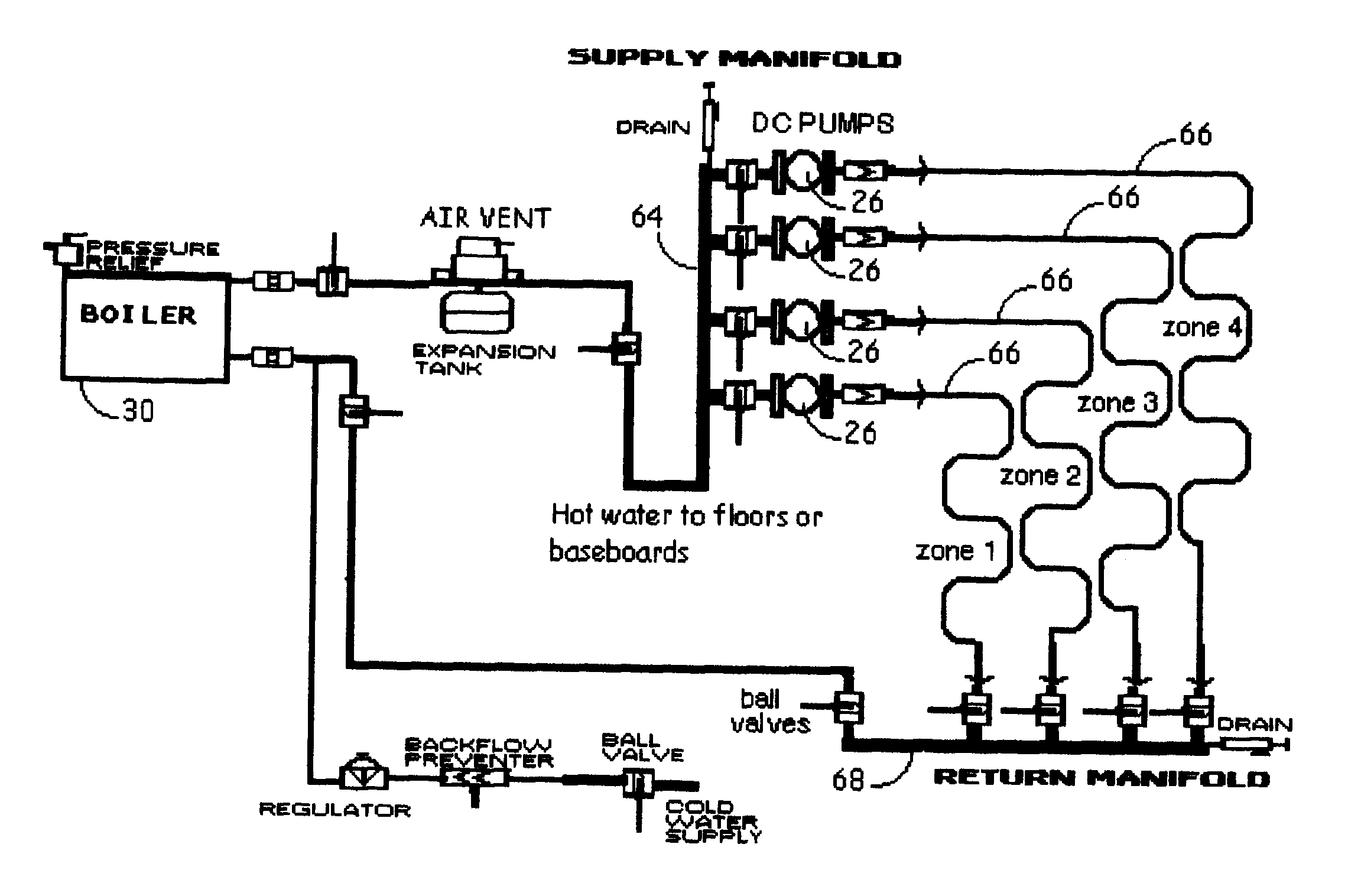
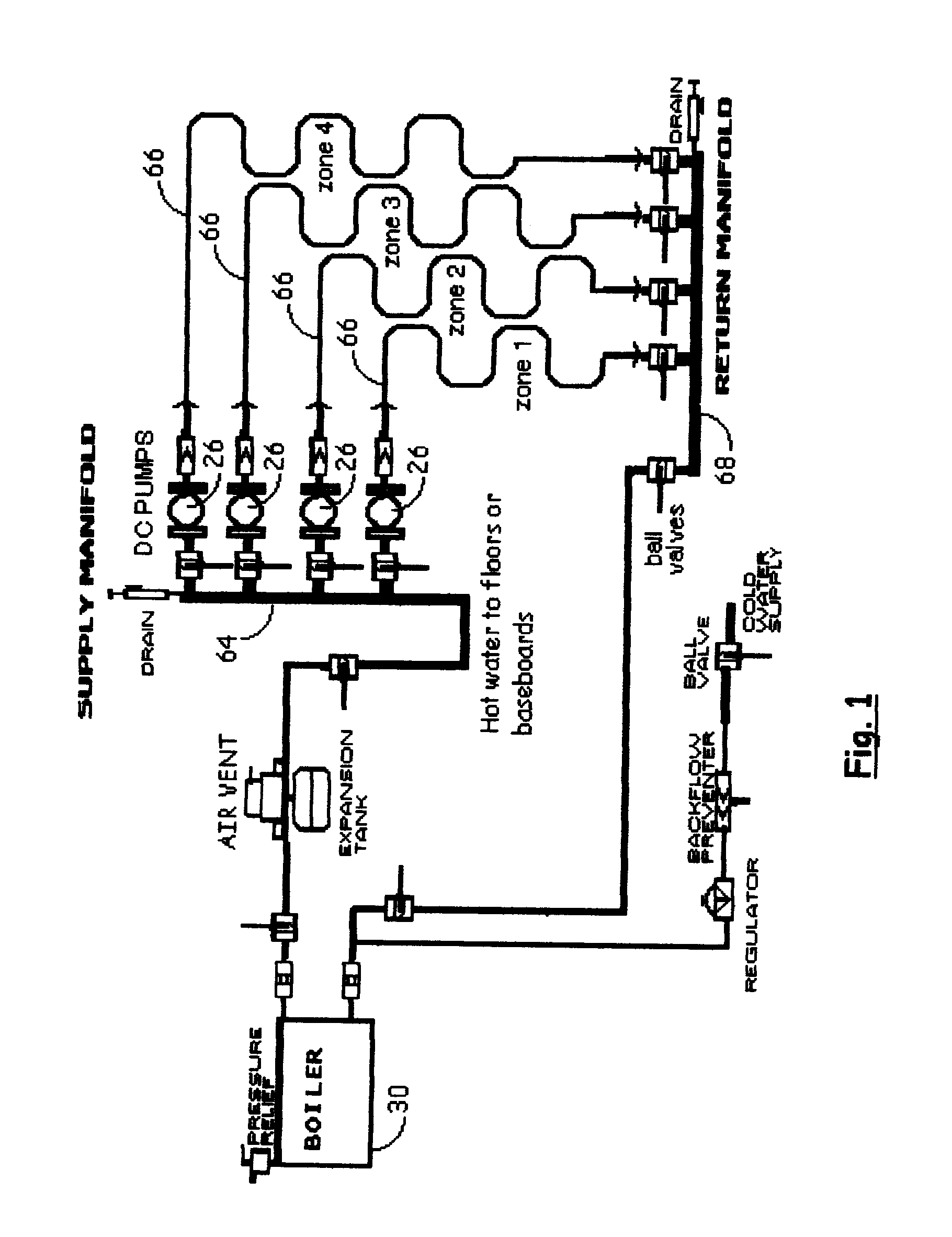
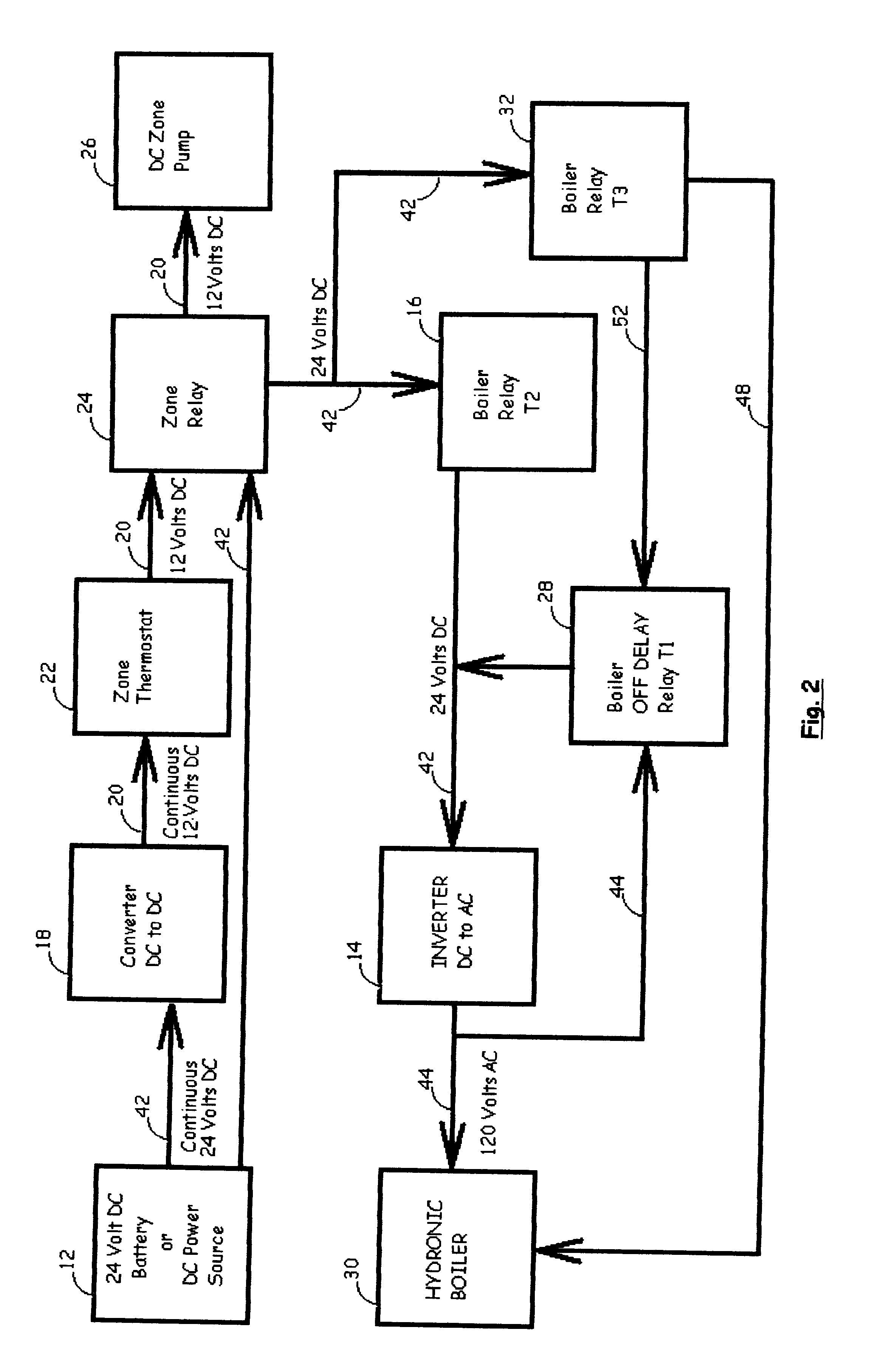
The preferred embodiment of the hydronic boiler system control is shown in FIGS. 1, 2, and 3. The invention comprises a method and apparatus for controlling the normal operation of a heating system, (including AC powered, gas-burning hot water boiler, multi-zone systems) using DC battery 12 power or a DC power source as the primary continuous source of electricity, that provides control functions which minimize the consumption of electric power, in order to extend the life of the batteries and maximize the run-time of the heating system.

The apparatus contains a small DC to AC inverter 14 such as Tumbler Technologies Model 24-15013, or the like, dedicated to provide AC power to boiler 30. DC to AC inverter 14 is switched on by inverter relay 16 only when needed, thereby eliminating the "phantom electric load" consumed by most boilers when they are standing by.

A DC to DC converter 18 is included in the apparatus to provide 12 volts DC 20 power to zone thermostats 22, thereby eliminat...


PUM


Abstract

A method and apparatus for controlling the normal operation of a hydronic heating system, (including AC powered, gas-burning hot water boiler, multi-zone systems) using a DC power source, such as battery power, as the primary continuous source of electricity. Control functions minimize the consumption of electric power during normal operation, and eliminate standby electric consumption in order to extend the life of the batteries and maximize the run-time of the heating system. A DC to DC converter supplies low voltage DC power to the zone thermostats, and also supplies the proper voltage through zone relays to operate DC zone pumps. By allowing the use of DC power for the thermostats and zone pumps, the system eliminates the need for transformers, zone valves, and AC circulators, resulting in a large savings in electrical consumption and the elimination of the standby electric demand ("phantom load") common in conventional hydronic heating systems. A DC to AC inverter is dedicated to supply AC power for a hydronic (hot water) boiler. The inverter is switched on by relays only when needed, thereby eliminating the "phantom electric load" consumed by most boilers when standing by. A time delay relay circuit allows the boiler to go through its proper shutdown sequence before power is removed. This control system does not require any internal modification to the other heating system components.

Description

1. Field of the Invention (Technical Field)The invention relates to heating system controls and more particularly to an apparatus and method of controlling hydronic and gas-fired hot-water space-heating systems utilizing DC or battery power.2. Background ArtControl devices for heating systems are not new in the art. However, systems that are presently available utilize AC power sources that require standby electrical loads. These systems are inherently inefficient. Some prior art references illustrate this.U.S. Pat. No. 5,622,221 to Genga, Jr., et al. discloses a control device for a multi zone hydronic boiler heating system using zone pumps. Genga, Jr. et al. discloses control system circuitry that is integrated into each individual zone pump requiring data-buss wiring between the pumps. The present invention is a central control system requiring only 2-conductor electric power wiring to the pumps. The main purpose of this prior art system is to provide priority zone control that i...

Claims


Application Information

Patent Timeline
IPC IPC(8): F24D19/10F24D19/00
CPCF24D19/1009F24D19/1012Y02B30/745Y02B30/70
Inventor STICKNEY, BRISTOL L.SINDELAR, ALLAN L.
Owner STICKNEY BRISTOL L
Why Eureka
Try Eureka